ดาวน์โหลดงานนำเสนอ
งานนำเสนอกำลังจะดาวน์โหลด โปรดรอ

1
LAB # 2 : FLOW IN PIPE Section 6
Mechanical Engineering Experimentation and Laboratory I LAB # 2 : FLOW IN PIPE Section 6 Members 1 นาย พิชชากร วัชรานุรักษ์ 2 นาย มารวย อนันต์สุขเกษม 3 นางสาว มาริษา ปรีชาสุข 4 นางสาว สิภาลักษณ์ ตั้งเจริญสุขจีระ 5 นางสาว รัมภา ชัยจินดา Third Year, Semester 1, year 2009, ME Chula

2
2103390 Mechanical Engineering Experimentation and Laboratory I
Introduction การไหลภายในท่อ สามารถพบได้ทั่วไปในงานทางด้านวิศวกรรม ซึ่งถูกใช้ในการส่งถ่ายของไหลจากที่หนึ่งไปยังอีกที่หนึ่ง เช่น การส่งน้ำประปาผ่านท่อไปใช้ในแหล่งชุมชน การขนส่งน้ำมันดิบผ่านท่อไปยังโรงกลั่น การส่งอากาศจากเครื่องปรับอากาศผ่านท่อไปยังส่วนต่างๆภายในอาคาร งานทางวิศวกรรมด้านอื่นๆ แรงเสียดทานในการไหลในท่อ เปลี่ยนพลังงานกลไปเป็นพลังงานความร้อน ก่อให้เกิดการสูญเสียพลังงาน LABORATORY No. 2 : Flow In Pipe : Section 6

3
2103390 Mechanical Engineering Experimentation and Laboratory I
Motivation ความเสียดทานของของไหลในการไหล ทำให้เกิดการสูญเสียของพลังงานทางกล ( Mechanical energy loss ) โดยที่ การไหลของระบบอยู่ภายใต้เงื่อนไขคงตัว (Steady condition) พลังงานที่ให้ของไหลเกิดจาก pump ( หรือ compressor ) ซึ่งขึ้นอยู่กับ Mechanical energy loss ดังนั้น การสูญเสียพลังงานกลของของไหลจึงเป็นสิ่งที่สำคัญในการออกแบบระบบท่อ LABORATORY No. 2 : Flow In Pipe : Section 6
 โดยที่ การไหลของระบบอยู่ภายใต้เงื่อนไขคงตัว (Steady condition) พลังงานที่ให้ของไหลเกิดจาก pump ( หรือ compressor ) ซึ่งขึ้นอยู่กับ Mechanical energy loss. ดังนั้น การสูญเสียพลังงานกลของของไหลจึงเป็นสิ่งที่สำคัญในการออกแบบระบบท่อ. LABORATORY No. 2 : Flow In Pipe : Section 6.")
4
2103390 Mechanical Engineering Experimentation and Laboratory I
Objectives อัตราการสูญเสียพลังงานกล (mechanical power loss) กับ อัตราการไหล (Flow rate) Related Dimensionless ความดัน (Static pressure) กับตำแหน่งตามแนวการไหล friction factor กับReynolds number LABORATORY No. 2 : Flow In Pipe : Section 6
 กับ อัตราการไหล (Flow rate) Related. Dimensionless. ความดัน (Static pressure) กับตำแหน่งตามแนวการไหล. friction factor กับReynolds number. LABORATORY No. 2 : Flow In Pipe : Section 6.")
5
Experiment Background
Mechanical Engineering Experimentation and Laboratory I Experiment Background 1 2 Conservation of Energy Equation Assumptions 1.Steady-state 2.Incompressible flow 3.Fully-developed flow 4.Neglect minor losses 5.No changes in elevation Mechanical Energy Pressure Energy Kinetic Energy Potential Energy LABORATORY No. 2 : Flow In Pipe : Section 6

6
Experiment Background
Mechanical Engineering Experimentation and Laboratory I Experiment Background 2 1 LABORATORY No. 2 : Flow In Pipe : Section 6

7
2103390 Mechanical Engineering Experimentation and Laboratory I
Experiment Setup Flow Disturbance Pressure Tab Flow Speculator Oil Reservoir Rotameter Pressure Transducer Setting Chamber Test Pipe Valve Pump Pipe Flow Apparatus Description: Convert & display unit of static pressure measured from pressure tab Storage of oil - fluid in pipe flow apparatus Determining the characteristic of flow by observation The system interested Imparts power (from motor) to fluid Flow rate measurement Measurement of static pressure Initially configuration of inlet flow Adjusting the desirable flow rate Turbulant triggering LABORATORY No. 2 : Flow In Pipe : Section 6
 to fluid. Flow rate measurement. Measurement of static pressure. Initially configuration of inlet flow. Adjusting the desirable flow rate. Turbulant triggering. LABORATORY No. 2 : Flow In Pipe : Section 6.")
8
2103390 Mechanical Engineering Experimentation and Laboratory I
Experiment Setup อุปกรณ์ทดสอบการไหลในท่อ (Pipe flow Apparatus) ของไหลที่ใช้ทดสอบ : น้ำมัน ทำการวัดระยะเพื่อกำหนดตำแหน่งของ pressure tab ทั้ง 18 ตำแหน่ง ตลับเมตร หาค่าความหนืด (Viscosity) กำหนดรูปแบบการไหลที่สนใจ (Laminar or Turbulent flow) ด้วยแท่ง disturbance กำหนดอัตราการไหลที่สนใจ 5 ค่า อ่านค่าความดันสถิตย์แต่ละตำแหน่ง pressure tab หาค่าความถ่วงจำเพาะ (Specific Gravity) สังเกตการไหลของน้ำมันที่ออกจากท่อ Rotameter Pressure Transducer ข้อมูลเก่า ปี 2550 Hydrometer วิเคราะห์ผลการทดลอง และสรุปผลการทดลอง LABORATORY No. 2 : Flow In Pipe : Section 6
 ของไหลที่ใช้ทดสอบ : น้ำมัน. ทำการวัดระยะเพื่อกำหนดตำแหน่งของ pressure tab ทั้ง 18 ตำแหน่ง. ตลับเมตร. หาค่าความหนืด. (Viscosity) กำหนดรูปแบบการไหลที่สนใจ. (Laminar or Turbulent flow) ด้วยแท่ง disturbance. กำหนดอัตราการไหลที่สนใจ 5 ค่า. อ่านค่าความดันสถิตย์แต่ละตำแหน่ง pressure tab. หาค่าความถ่วงจำเพาะ. (Specific Gravity) สังเกตการไหลของน้ำมันที่ออกจากท่อ. Rotameter. Pressure Transducer. ข้อมูลเก่า. ปี Hydrometer. วิเคราะห์ผลการทดลอง. และสรุปผลการทดลอง. LABORATORY No. 2 : Flow In Pipe : Section 6.")
9
Experiment condition อัตราการไหล : อยู่ในช่วง 30 - 70 l/min
Mechanical Engineering Experimentation and Laboratory I Experiment condition อัตราการไหล : อยู่ในช่วง l/min รูปแบบการไหล Laminar flow ไม่มีการดัน flow disturbance Turbulent flow มีการดัน flow disturbance Reynolds number Laminar flow : 1900 ≤ ReD ≤ 4400 Turbulent flow : 3100 ≤ ReD ≤ 4400 LABORATORY No. 2 : Flow In Pipe : Section 6

10
2103390 Mechanical Engineering Experimentation and Laboratory I
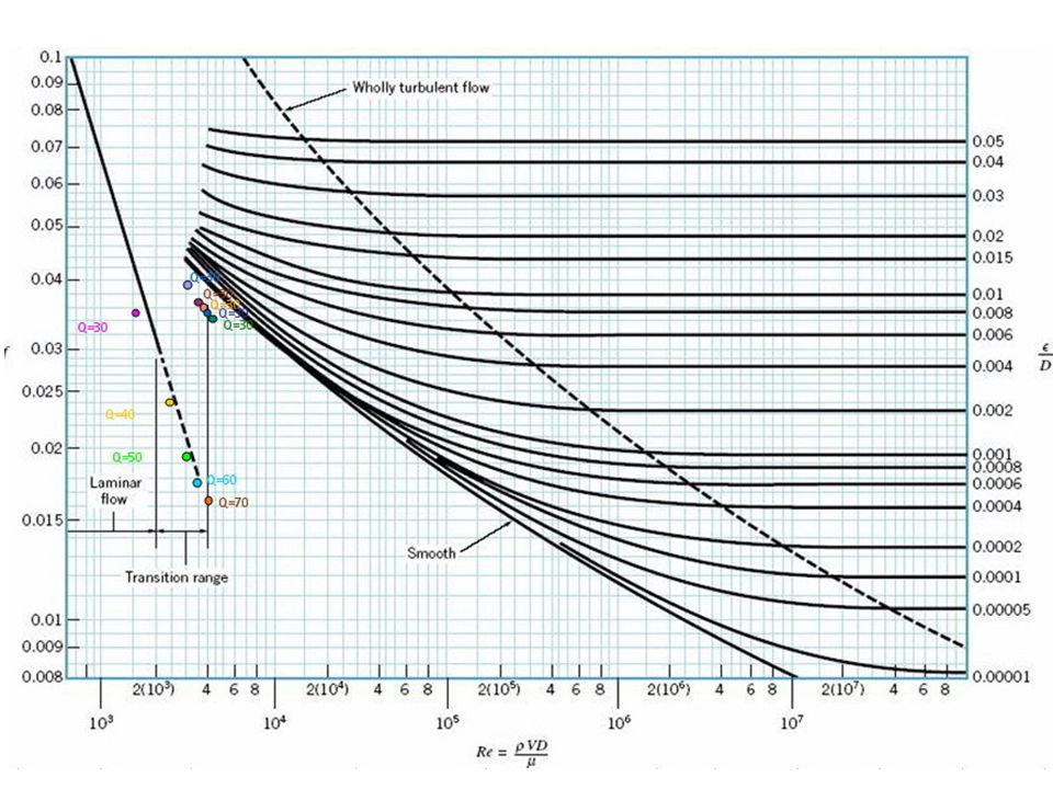
Experiment Result กราฟแสดงความสัมพันธ์ระหว่างความดัน (Static pressure) กับตำแหน่งตามแนวการไหล กราฟแสดงความสัมพันธ์ระหว่างอัตราการสูญเสียพลังงานกล ( mechanical Energy loss) กับ อัตราการไหล ( Flow rate ) กราฟแสดงความสัมพันธ์ระหว่าง friction factor กับ Reynolds number LABORATORY No. 2 : Flow In Pipe : Section 6
 กับตำแหน่งตามแนวการไหล. กราฟแสดงความสัมพันธ์ระหว่างอัตราการสูญเสียพลังงานกล ( mechanical Energy loss) กับ อัตราการไหล ( Flow rate ) กราฟแสดงความสัมพันธ์ระหว่าง friction factor กับ Reynolds number. LABORATORY No. 2 : Flow In Pipe : Section 6.")
11
Pressure vs Distance for Laminar Flow
Larminar flow, Q = 70L/min

12
Pressure vs Distance Turbulent flow, Q = 70L/min
Larminar flow, Q = 70L/min

13
2103390 Mechanical Engineering Experimentation and Laboratory I
(1 liter/s) LABORATORY No. 2 : Flow In Pipe : Section 6
 LABORATORY No. 2 : Flow In Pipe : Section 6.")
15
วิเคราะห์ Velocity profile
Mechanical Engineering Experimentation and Laboratory I Discussion วิเคราะห์ Velocity profile ที่อัตราการไหลต่ำๆ หรือReynolds numberต่ำๆ นั้น ถึงแม้ว่าจะดัน flow disturber เข้าไปสุดแล้วก็ตาม flowที่ออกจากปลายท่อก็ยังคงเป็น Laminar อยู่ LABORATORY No. 2 : Flow In Pipe : Section 6

16
2103390 Mechanical Engineering Experimentation and Laboratory I
Conclusion ความดันจะมีค่าลดลงเมื่อระยะทางตามแนวการไหลเพิ่มมากขึ้น อัตราการไหลที่สูงกว่าจะมีค่าความดันลดลงตามแนวการไหลมากกว่า การไหลแบบ Turbulent จะมีค่าความดันลดลงตามแนวการไหลสูงกว่าการไหลแบบ Laminar อัตราการสูญเสียพลังงานกลมีค่าสูงขึ้นตามอัตราการไหลที่มากขึ้น การไหลแบบ Turbulent จะมีอัตราการสูญเสียพลังงานกลมากกว่าการไหลแบบ Laminar ค่า Friction factor จะมีค่าลดลงเมื่อ Reynolds number มากขึ้นหรือมีอัตราการไหลมากขึ้น ที่อัตราการไหลเท่ากัน การไหลแบบTurbulent จะมีค่า Friction factor หรืออัตราการสูญเสียพลังงานกลสูงกว่าการไหลแบบ Laminar LABORATORY No. 2 : Flow In Pipe : Section 6

งานนำเสนอที่คล้ายกัน


 Group>")


>")


>")