ดาวน์โหลดงานนำเสนอ
งานนำเสนอกำลังจะดาวน์โหลด โปรดรอ

1
Boolean algebra George Boole ( ) นักคณิตศาสตร์ชาวอังกฤษผู้คิดค้น Boolean Algebra ซึ่งเป็นวิชาพีชคณิตใช้เฉพาะกับ Logic เมื่อปี ค.ศ จากนั้น Boolean Algebra ก็ได้รับ การวิวัฒนาการเรื่อยๆ มาจนกระทั่งปี ค.ศ. 1938 จึงถูกนำมาใช้ในวิชา Theory of switching circuits โดย C. E. Shannon ถึงแม้ว่าผลงานของ Shannon จะหนักไปในด้านการออกแบบสวิทซ์ แม่เหล็กไฟฟ้า (Electromechanical Relay Network) แต่ก็สามารถที่จะปรับปรุงมา ใช้งานได้ดีสำหรับวงจร Solid-state electronic ทุกวันนี้
 แต่ก็สามารถที่จะปรับปรุงมา. ใช้งานได้ดีสำหรับวงจร Solid-state. electronic ทุกวันนี้")
2
Boolean Algebra Boolean Algbera is a mathematical Model for digital logic circuits. Boolean Algebra is a system <B, V, P> B={0,1} is the set of values1 V is the set of variables P={+, •, ΄} is the set of operators (basic functions) defined by the truth tables as follows
 defined by the truth tables as follows.")
3
Boolean values Boolean Algebra แตกต่างไปจากวิชาพีชคณิตที่เรารู้จักกัน ค่า ตัวแปรต่างๆ จะมีได้เพียง 2 ค่าเท่านั้น คือ false or true 0 or 1 low or high กฎเกณฑ์บางอันก็คล้ายคลึงกันบางอันก็ต่างกันมาก กฎต่างๆ ของ Boolean algebra ที่สำคัญมีดังนี้

4
Boolean operations not or and xor (exclusive or) nand (not and)
nor (not or)
")
5
Not Note: Some people write x’ instead of x The “bubble” (or “bobble”) means “not”.
 means not .")
6
And Notes: Some people write a^b or a&b.
The gate is shaped like a “D” as in “anD”.

7
Or Note: Some people write ab or a|b.

8
Exclusive-or (xor)
")
9
Nand

10
Nor

11
Boolean Algebra The axioms (or postulates) of Boolean Algebra
(A1) X=0 หรือ (A1’) X=1 (A2) If X=0, then X’=1 (A2’) If X=1, then X’=0 (A3) 0·0 = 0 (A3’) 1+1 = 1 (A4) 1·1 = 1 (A4’) 0+0 = 0 (A5) 0·1 = 1·0 = 0 (A5’) 1+0 = 0+1 = 1 Note We use a prime (’) to denote an inverter’s function.
 X=0 หรือ (A1’) X=1. (A2) If X=0, then X’=1 (A2’) If X=1, then X’=0. (A3) 0·0 = 0 (A3’) 1+1 = 1. (A4) 1·1 = 1 (A4’) 0+0 = 0. (A5) 0·1 = 1·0 = 0 (A5’) 1+0 = 0+1 = 1. Note We use a prime (’) to denote an inverter’s function.")
12
Theorems involving a single variable: (T1) X+0 = X. (T1’) X·1 = X
Theorems involving a single variable: (T1) X+0 = X (T1’) X·1 = X (Identities) (T2) X+1 = 1 (T2’) X·0 = 0 (Null elements) (T3) X+X = X (T3’) X·X = X (Idempotency) (T4) (X’)’ = X (Involution) (T5) X+X’ = 1 (T5’) X·X’ = (complements) These theorems can be proved to be true. Let us prove T1: [X=0] 0+0=0 (true, according to A4’) [X=1] 1+0=1 (true, according to A5’)
 X+0 = X (T1’) X·1 = X (Identities) (T2) X+1 = 1 (T2’) X·0 = 0 (Null elements) (T3) X+X = X (T3’) X·X = X (Idempotency) (T4) (X’)’ = X (Involution) (T5) X+X’ = 1 (T5’) X·X’ = 0 (complements) These theorems can be proved to be true. Let us prove. T1: [X=0] 0+0=0 (true, according to A4’) [X=1] 1+0=1 (true, according to A5’)")
13
Theorems involving two or three variables: (T6). X+Y = Y+X
Theorems involving two or three variables: (T6) X+Y = Y+X (T6’) X·Y = Y·X (Commutativity) (T7) (X+Y)+Z = X+(Y+Z) (T7’)(X·Y)·Z = X·(Y·Z) (Associativity) (T8) X·Y+X·Z = X·(Y+Z) (T8’) (X+Y)·(X+Z) = X+Y·Z (Distributivity) (T9) X+X·Y = X (T9’) X·(X+Y) = X (Covering) (T10) X·Y+X·Y’ = X (T10’)(X+Y)·(X+Y’) = X (Combining)
 X+Y = Y+X (T6’) X·Y = Y·X (Commutativity) (T7) (X+Y)+Z = X+(Y+Z) (T7’)(X·Y)·Z = X·(Y·Z) (Associativity) (T8) X·Y+X·Z = X·(Y+Z) (T8’) (X+Y)·(X+Z) = X+Y·Z (Distributivity) (T9) X+X·Y = X (T9’) X·(X+Y) = X (Covering) (T10) X·Y+X·Y’ = X (T10’)(X+Y)·(X+Y’) = X (Combining)")
14
(T11). X·Y+X’·Z+Y·Z = X·Y+X’·Z. (Consensus) (T11’)
(T11) X·Y+X’·Z+Y·Z = X·Y+X’·Z (Consensus) (T11’) (X+Y)·(X’+Z)·(Y+Z) = (X+Y)·(X’+Z) (T12) (X1·X2· ... ·Xn)’ = X1´+X2´ Xn’ (T12’) (X1+X Xn)’ = X1´·X2´· ... ·Xn’ ( DeMorgan’s theorems) (T13) X + X’ · Y = X + Y (T13’) X · (X’ + Y) = X · Y Attention to theorem T8’ which is not true for integers and reals. T9 and T10 are used in the minimisation of logic functions.
 X·Y+X’·Z+Y·Z = X·Y+X’·Z (Consensus) (T11’) (X+Y)·(X’+Z)·(Y+Z) = (X+Y)·(X’+Z) (T12) (X1·X2· ... ·Xn)’ = X1´+X2´ Xn’ (T12’) (X1+X Xn)’ = X1´·X2´· ... ·Xn’ ( DeMorgan’s theorems) (T13) X + X’ · Y = X + Y. (T13’) X · (X’ + Y) = X · Y. Attention to theorem T8’ which is not true for integers and reals. T9 and T10 are used in the minimisation of logic functions.")
15
The most basic representation of a logic function is a truth table.
A truth table lists the output of the circuit for every possible input combination. There are 2n rows in a truth table for an n-variable function.

16
Gates Three basic gates (AND, OR, NOT) are sufficient to build any
combinational digital logic system.

17
Gates (2) Two more logic functions are obtained by combining
NOT with an AND or OR function in a single gate.

18
1

19
Equivalent gates according to DeMorgan’s theorem

20
An electrical model In a parallel arrangement electricity will flow through if one or other switch is closed. In a series arrangement both switches must be closed. a b or a a + b b a b a b a · b and

21
When SW1 AND SW2 are closed. F = SW1&SW2 When SW1 OR SW2 are closed. F = SW1+SW2

22
Finding the Boolean expression for a circuit
(p+q) ·(p ·q)’ or (p+q) ·(p ·q)
 ·(p ·q)’ or (p+q) ·(p ·q)")
23
a b c f

24
Constructing circuits for Boolean expressions
To construct a circuit for the expression p'q +q'

25
Simplification of Boolean Functions
General Boolean functions of n variables can be represented by Boolean expressions Truth tables showing the function values for all input combinations Boolean functions can be implemented directly from their expressions, but Complicated expressions may results in circuits Using more gates than necessary or Having longer accumulative gate delay than necessary

26
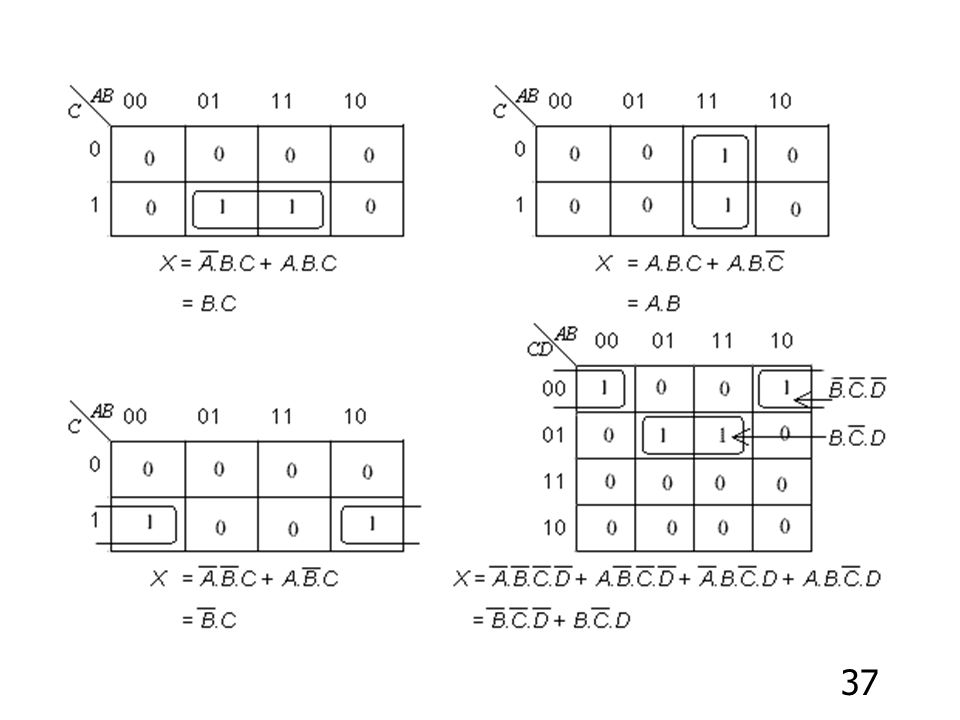
การทำ Logic circuits ให้ง่าย
วิธีดังนี้ ทำโดยนำทฤษฎีต่างๆ มาใช้ในการลดรูปของสมการให้น้อย ลง ตัวอย่าง จงลดรูปสมการ A + A · B + A’ · B A + A · B + A’ · B = (A + A · B) + A’ · B (T9) = A + A’ · B (T13) = A + B
 + A’ · B (T9) = A + A’ · B (T13) = A + B.")
27
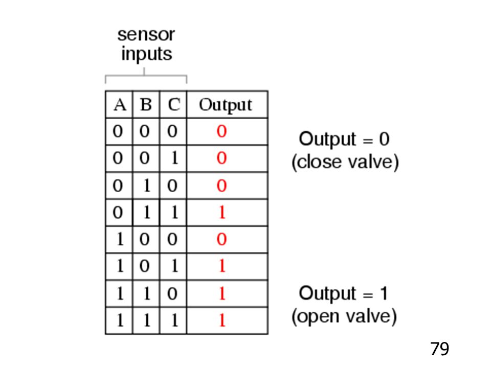
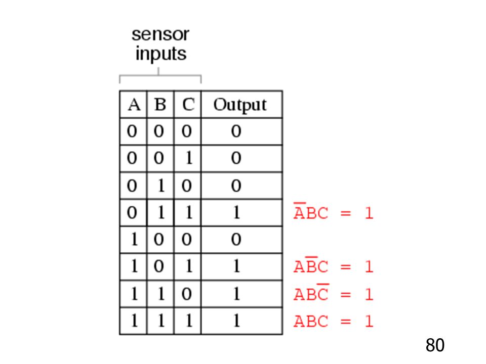
Minterms (Sum-of-Products) of n variables
เป็นอีกวิธีที่จะทำให้ Logic circuits ง่ายลง ซึ่งมีวิธี ทำคือ จะพิจารณา Truth table ที่ได้ผลลัพธ์เป็น 1 โดยนำตัวแปรมาทำการ AND แล้ว OR เพื่อสร้างเป็น Boolean expression ซึ่งมีรูปแบบเป็นผลบวกของผล คูณ (Sum-of-Products) โดยกำหนดค่าดังนี้ A ,B ,C = 1 A’,B’,C’ = 0 ตัวอย่าง
 โดยกำหนดค่าดังนี้ A ,B ,C = 1. A’,B’,C’ = 0. ตัวอย่าง.")
28
X Y Z F * * * * We have f = x’y’z’ + x’yz’ + x y’z + x y z f = x’y’z’ + x’yz’ + x y’z + x y z

29
But the sum of product of minterms can be further simplified to reduce
the number of product terms and the number of inputs of the gates example f = x’y’z’ + x’yz’ + xy’z + xyz = x’z’(y’+y) + xz(y’+y) = x’z’ + xz But, how do we reach the simplest form systematically?
 + xz(y’+y) = x’z’ + xz. But, how do we reach the simplest form systematically")
30
Maxterms (Product-of-Sums) of n variables
- Maxterm boolean expression is developed from the 0s in the output column of the truth table. For each 0 in the output column, an Ored term is developed. - Note that the input variables are inverted and then Ored. A ,B ,C = 0 A’,B’,C’ = 1

31
Input Output C B A F * * Maxterm Boolean expression : f = (c’+b+a) · (c’+b’+a’)
 · (c’+b’+a’)")
32
Input Output C B A F จงหา Minterm Boolean expression Maxterm Boolean expression

33
Karnaugh Map Simplication
Karnaugh maps เป็นอีกวิธีที่จะทำให้ Logic circuits ง่ายลง ซึ่งมีวิธีดังนี้ two variables B’(0) B(1) Input Output A B Y A’(0) A (1) Y = A + B
 B(1) Input Output. A B Y A’(0) 1. A (1) 1 1. Y = A + B.")
34
- three variables and four variables
C’(0) C(1) A’B’(00) A’B (01) AB (11) AB’(10) (C)
 C(1) A’B’(00) A’B (01) AB (11) AB’(10) (C)")
35
three variables Input Output C B A F 0 0 0 1 0 0 1 1 0 1 0 1 0 1 1 1
C’(0) C(1) C B A F A’B’(00) A’B (01) AB (11) AB’ (10) 1 F = C’ + A’B + AB’
 C(1) C B A F A’B’(00) A’B (01) AB (11) AB’ (10) F = C’ + A’B + AB’")
36
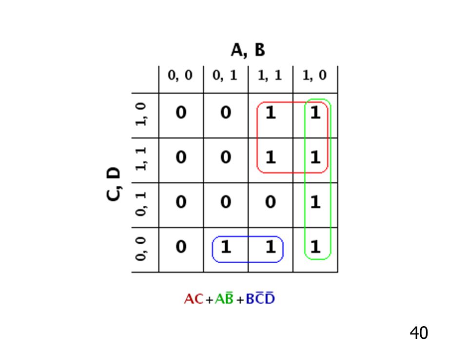
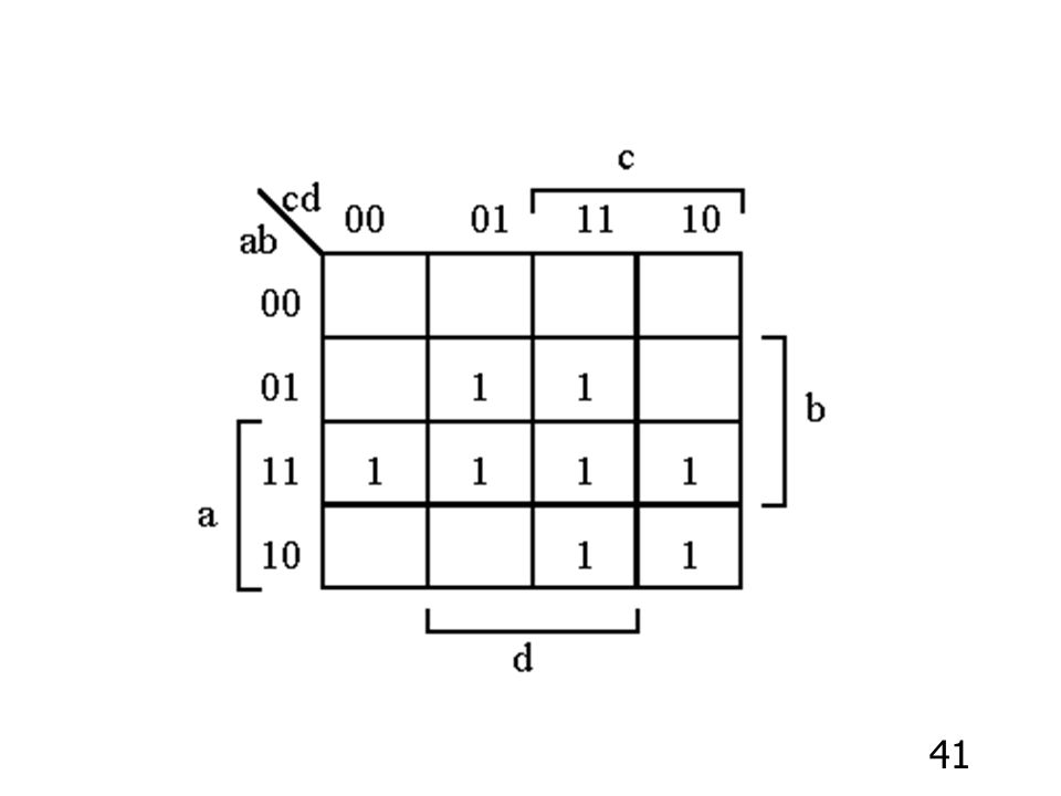
four variables Inputs Output Y = AC + A’C’D’ A B C D Y 0 0 0 0 1
C’D’ C’D CD CD’ 1 A’B’(00) A’B (01) AB (11) AB’ (10) 1 1 1 1 1 Y = AC + A’C’D’
 A’B (01) AB (11) AB’ (10) Y = AC + A’C’D’")
44
Mapping with maxterm expression
Input Output C C’ A B C F A+B (0+0) A+B’ (0+1) A’+B’(1+1) A’+B (1+0) 1 F = (B + C) · (A’+C)
 A+B’ (0+1) A’+B’(1+1) A’+B (1+0) 1. F = (B + C) · (A’+C)")
45
Maxterm Minterm

46
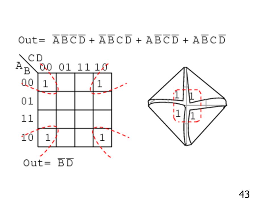
Don’t cares on Karnaugh maps
ในวงจร logic บางวงจรสามารถออกแบบโดยไม่ระบุ output บางตัวว่า เป็น 1หรือ 0 Output ที่ไม่สนใจหรือไม่สามารถระบุ output ได้นี้ เรียกว่า “Don’t care”

47
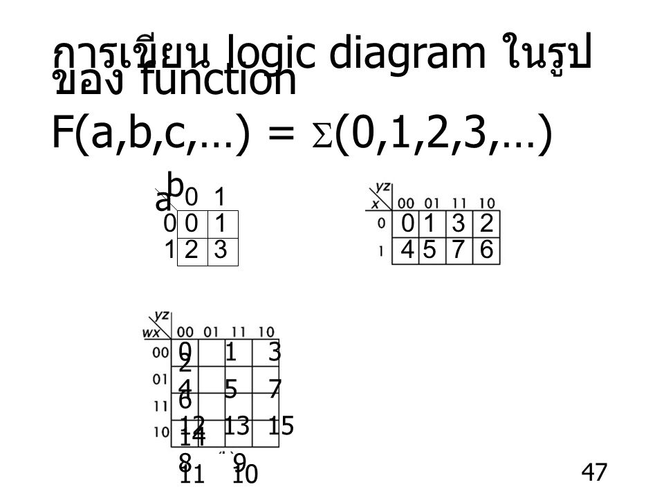
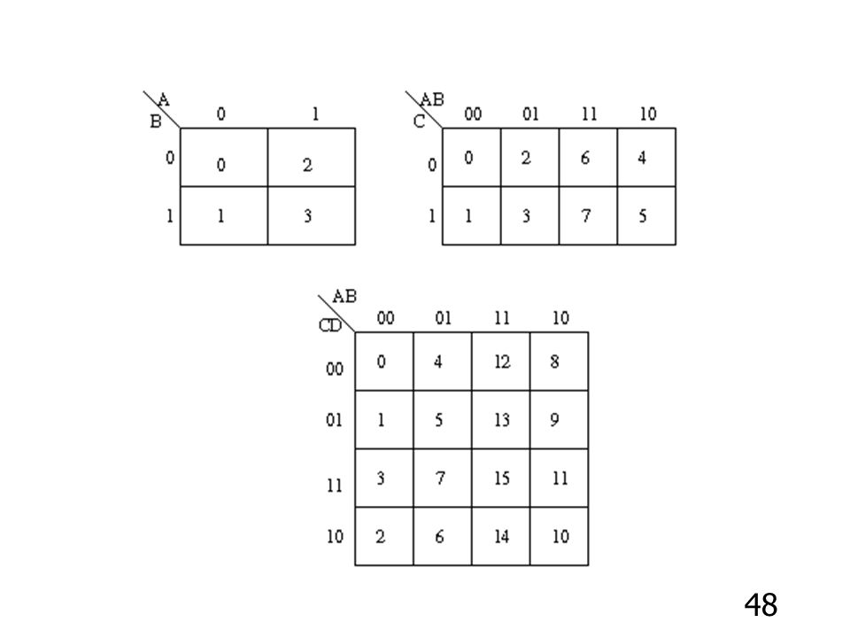
การเขียน logic diagram ในรูปของ function F(a,b,c,…) = S(0,1,2,3,…)
0 1 0 0 1 1 2 3
49
Inputs ตำแหน่ง A B C D

50
ตัวอย่าง F(a,b,c) = S(3,4,6,7) b bc a 1 a c
 = S(3,4,6,7) b bc a a c")
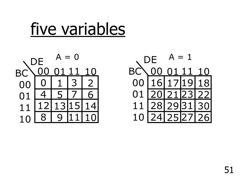
51
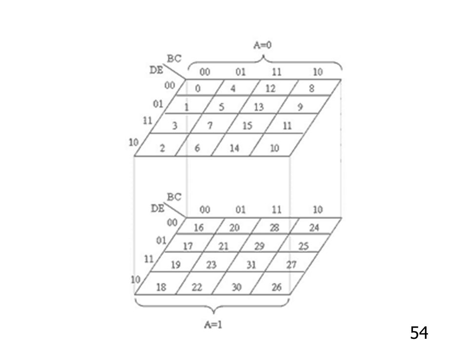
five variables DE BC 00 01 11 10 DE BC 00 01 11 10 00 4 12 8 01 1 5 13
4 12 8 01 1 5 13 9 11 3 7 15 10 2 6 14 00 16 20 28 24 01 17 21 29 25 11 19 23 31 27 10 18 22 30 26
52
F(A,B,C,D,E) (0,2,5,7,13,15,17,18,19,21,23,29,31) A = 0 A = 1 DE BC 00 01 11 10 DE BC 00 01 11 10 00 1 01 11 10 00 01 1 11 10

53
F(A,B,C,D,E) (0,2,5,7,13,15,17,18,19,21,23,29,31) A = 0 A = 1 DE BC 00 01 11 10 DE BC 00 01 11 10 00 1 01 11 10 00 01 1 11 10 F(A,B,C,D,E) หรือ X = CE + B’C’DE’ +AB’E+A’B’C’E’ 53
 หรือ X = CE + B’C’DE’ +AB’E+A’B’C’E’ 53.")
56
F(A,B,C,D,E) หรือ X = CE + B’C’DE’ +AB’E+A’B’C’E’
 หรือ X = CE + B’C’DE’ +AB’E+A’B’C’E’")
57
Six-Variable K-Map EF CD 00 01 11 10 EF CD 00 01 11 10 00 4 12 8 01 1
4 12 8 01 1 5 13 9 11 3 7 15 10 2 6 14 00 16 20 28 24 01 17 21 29 25 11 19 23 31 27 10 18 22 30 26 EF CD 00 01 11 10 EF CD 00 01 11 10 AB = 10 AB = 11 00 32 36 44 40 01 33 37 45 41 11 35 39 47 43 10 34 38 46 42 00 48 52 60 56 01 49 53 61 57 11 51 55 63 59 10 50 54 62 58

58
Six-Variable K-Map EF CD 00 01 11 10 00 1 01 11 10 EF CD 00 1 01 11 10

59
EF AB = 00 CD = 00 10 AB = 01 11 10 AB = 11 AB = 10

60
Combinational circuits แบบง่ายๆ
Half-Adder ใช้ในการบวกเลขฐานสอง Input Output S = Sum C = Carry X Y C S X S Y C

61
Adder Design Example To design the 4-bit binary adder, we first design two types of adders: a half adder and a full adder. A half adder is a combinational circuit that performs the addition of two bits (no carry in). 1 bit Half Adder A B S Co Boolean expressions for S and Co: S = AB’+A’B = A Å B Co = AB A B S Co Logic diagram:
. 1 bit Half Adder. A. B. S. Co. Boolean expressions for S and Co: S = AB’+A’B = A Å B. Co = AB A B S Co Logic diagram:")
62
Adder Design Example Full adder: a combinational circuit that performs the addition of 3 bits (two bits and a carry-in bit). Ci Ai Bi Si Ci+1 Ai Si Bi FA Ci Ci+1 S = A Å B Å C C = ABC’ +A’BC +AB’C+ABC = AB(C +C’)+C(AB’ + A’B) = AB + C(A + B)
+C(AB’ + A’B) = AB + C(A + B)")
63
Full Adder Design Example
Full adder can be realized with two half adders and an OR gate, since Ci+1 can be expressed as: Ai Si Bi Ci+1 Ci

64
Binary Decoder Logic with n input lines and 2n output lines.
Only one output is a 1 for any given input. Binary Decoder n inputs 2n outputs

65
truth table for 2 to 4 decoder:
Note: Each output is a 2-variable minterm (X'Y', X'Y, XY' or XY) F0 = X'Y' F1 = X'Y F2 = XY' F3 = XY X Y X Y F 1 2 3
 F0 = X Y F1 = X Y. F2 = XY F3 = XY. X. Y. X. Y. F")
66
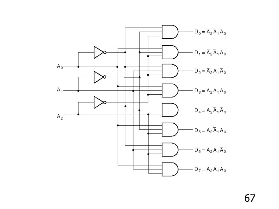
3-to-8-Line Decoder

69
Encoder 2n (or fewer) input lines and n output lines.
The output lines generate the binary code corresponding to the input value, assuming only one input is high. An encoder is the reverse function of a decoder

70
8-to-3-line Encoder 8-to-3 Encoder

71
Example: Octal-to-Binary Encoder

72
Code Converter Example
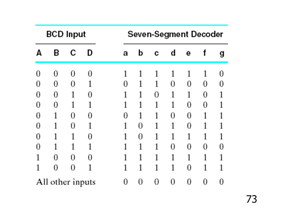
Design a circuit that converts a binary-coded-decimal (BCD) to the seven signals required to drive a seven-segment light-emitting diode (LED) display. Assuming the signal 1 illuminates the segment and a logic-0 signal turns off the segment
 to the seven signals required to drive a seven-segment light-emitting diode (LED) display. Assuming the signal 1 illuminates the segment and a logic-0 signal turns off the segment.")
74
Code Converter Example
Derive the Boolean function for each output - e.g., using the following K-map to derive the Boolean function for output a CD 01 AB 00 11 10 a = A’C + A’BD + A’B’D’+ AB’C’ 00 1 1 01 11 10

82
C’(0) C(1) A’B’(00) A’B (01) AB (11) AB’ (10) 1
 C(1) A’B’(00) A’B (01) AB (11) AB’ (10) 1 1 1")
83
การสร้างวงจรแสดง : ลูกเต๋า 6 ด้าน
ถ้าต้องการสร้างวงจรที่แสดงสัญลักษณ์ในการออกลูกเต๋าแต่ละหน้าดังนี้ โดยใช้ LED วางตามตำแหน่งเพื่อแสดงการออกลูกเต๋าที่ทอดได้ในแต่ละหน้า A B C D E F G

84
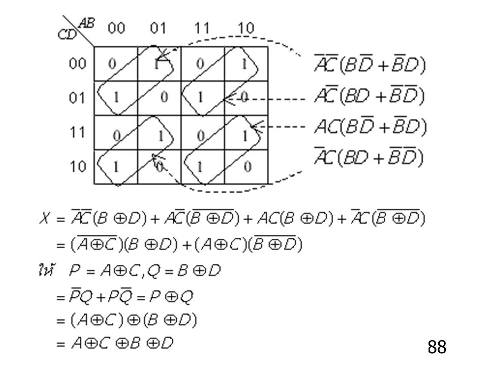
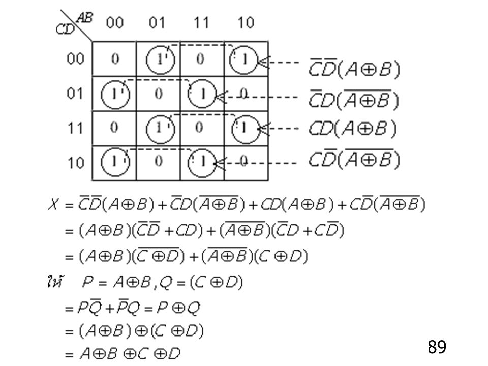
Karnaugh maps with XOR and XNOR

85
Truth table : A’B + AB’ = A + B
A B A’ B’ A’B AB’ A’B + AB’ A + B

86
XNOR :

87
Truth table : AB + A’B’ = (A + B)’
A B A’ B’ AB A’B’ AB + A’B’ (A + B)’
’")
งานนำเสนอที่คล้ายกัน


 ง30301 คณิตศาสตร์ดิสครีต.>")

 98.08% 100.02% จังหวัด.>")
 ปี 57 เกิด 3 จับ 2 ราย (66.67.00% ) คดีเท่ากัน ผลการจับกุมบรรลุเป้า ( เป้า 75.47 %)>")


