ดาวน์โหลดงานนำเสนอ
งานนำเสนอกำลังจะดาวน์โหลด โปรดรอ

1
Training Cisco Certified Network Associate (CCNA 640-802)
Mr.Kriangsak Namkot

2
Day 1 Internetworking Introduction to TCP/IP
Subnetting,Variable Length Subnet Masks(VLSMs),and Troubleshooting TCP/IP Internetworking Operating System(IOS) and Security Device Manager(SDM) Managing a cisco internetwork LAB Configuration
,and Troubleshooting TCP/IP. Internetworking Operating System(IOS) and Security Device Manager(SDM) Managing a cisco internetwork. LAB Configuration.")
3
Introduction to CCNA Exam

4
General Certifications

5
General Certifications

6
CCNA Certification

7
Cisco Icons and Symbols

8
Internetworking เป็นการเชื่อมโยงระบบเครือข่ายเข้าด้วยกัน เพื่อให้เครื่องในแต่ละเครือข่ายสามารถติดต่อถึงกันได้ Internet เป็นตัวอย่างหนึ่งของการทำ Internetworking สามารถเชื่อมโยงเครือข่ายทั้งโลกเข้าด้วยกัน โดยใช้โปรโตคอล TCP/IP Intranet เป็นการประยุกต์ใช้ Internet เฉพาะภายในองค์กร

9
Defining Components of the Network
Home Office Mobile Users Internet Note: The two connections between the same sites are for redundency. Emphasize: The type of connections typical in a home office may be asynchronous dial-up or ISDN BRI. Mobile users only use dial-up. Branch offices and Central sites have the connections just stated. In addition they may have leased lines and packet switched services, to list just a few. Branch Office Main Office

10
Defining the Components of a Network (cont.)
Branch Office Floor 2 Emphasize: Breaking up the corporate network into smaller components makes network design and management more managable. Transition: The next few pages a heirarchical model used in network design. Server Farm ISDN Floor 1 Telecommuter Remote Campus

11
Network Structure Defined by Hierarchy
Core Layer Distribution Layer Purpose: This page introduces the hierarchical model. Emphasize: This model has evolved from real-life experience in configuring very large networks. Campus network designs have traditionally placed basic network-level intelligence and services at the center of the network and shared bandwidth at the user level. Over the past few years distributed network services and switching has migrated to the user level. One approach to ensure a level of network performance is to segment the network into layers of functionality. These layers of functionality are defined by the following layers: Access Distribution Core Layer. This model permits enables designers to define building blocks that interconnect users and services. It is important to remember that the hierarchical model refers to conceptual layers that provide functionality. The actual demarcation between layers does not necessarily have to be a physical link. This demarcation can also refer to the backplane of a particular device Transition: The following describes the access layer of the hierarchical model. Access Layer

12
OSI Model Overview

13
OSI Model Overview Application (Upper) Layers Presentation Session
Transport Layer Layer 2 of 2: Purpose: This figure orients the students to the next set of concepts. Emphasize: The Data Link layer of the OSI reference model is implemented by Switches and Bridges. These devices encapsulate date in “frames”. The Network layer of the OSI reference model is implemented by Routers. These devices encapsulate data in ‘packets’. The Transport layer of the OSI reference model is implemented by various protocols; one of which is TCP. TCP uses ports and encapsulates the data in ‘segments’. Network Layer Data Flow Layers Data Link Physical

14
Role of Application Layers
EXAMPLES Telnet FTP ASCII EBCDIC JPEG Operating System/ Application Access Scheduling Application User Interface How data is presented Special processing such as encryption Presentation Keeping different applications’ data separate Session Slide 4 of 4: Purpose: This figure orients the students to the entire OSI model stack. Emphasize: The lower layers sit below the upper three layers. The remainder of this course is focused on the lower layers. Transition: The following discusses the physical layer of the OSI reference model. Transport Layer Network Layer Data Link Physical

15
Role of Data Flow Layers
Application Presentation EXAMPLES Session Reliable or unreliable delivery Error correction before retransmit TCP UDP SPX Transport Provide logical addressing which routers use for path determination IP IPX Network Slide 5 of 5: Purpose: This figure reviews the entire OSI model stack. Emphasize: The upper layers sit above the lower layers. Transition: The following discusses encapsulation and de-encalsulation. Combines bits into bytes and bytes into frames Access to media using MAC address Error detection not correction 802.3 / 802.2 HDLC Data Link Move bits between devices Specifies voltage, wire speed and pin-out cables EIA/TIA-232 V.35 Physical

16
Encapsulating Data PDU Segment Transport Network Packet
Application (Protocol Data Unit) Presentation PDU Session Upper Layer Data Segment Transport TCP Header Upper Layer Data Network Packet IP Header Data Purpose: This figure illustrates encapsulation. Emphasize: The protocol data units (PDUs) are the terms used in the industry and in this course to describe data at the different layers. Encapuslation is a key concept that illustrates how data is formatted prior to being sent across a link. This example is an illustration is Ethernet (or token ring) at the data link and physical layer and TCP/IP at the network and transport layers. Transition: The following discusses de-encalsulation. LLC Header Data FCS Data Link Frame MAC Header Data FCS Physical Bits
 Presentation. PDU. Session. Upper Layer Data. Segment. Transport. TCP Header. Upper Layer Data. Network. Packet. IP Header. Data. Purpose: This figure illustrates encapsulation. Emphasize: The protocol data units (PDUs) are the terms used in the industry and in this course to describe data at the different layers. Encapuslation is a key concept that illustrates how data is formatted prior to being sent across a link. This example is an illustration is Ethernet (or token ring) at the data link and physical layer and TCP/IP at the network and transport layers. Transition: The following discusses de-encalsulation. LLC Header. Data. FCS. Data Link. Frame. MAC Header. Data. FCS. Physical. Bits")
17
Introduction to TCP/IP
Department of Defense (DoD)
")
18
Introduction to TCP/IP

19
Introduction to TCP/IP
TCP (Transmission Control Protocol) is a set of rules (protocol) used along with the Internet Protocol (IP) to send data in the form of message units between computers over the Internet. While IP takes care of handling the actual delivery of the data, TCP takes care of keeping track of the individual units of data (called packets) that a message is divided into for efficient routing through the Internet. User Datagram Protocol (UDP) is one of the core protocols of the Internet protocol suite. Using UDP, programs on networked computers can send short messages sometimes known as datagrams (using Datagram Sockets) to one another. UDP is sometimes called the Universal Datagram Protocol or Unreliable Datagram Protocol.
 is a set of rules (protocol) used along with the Internet Protocol (IP) to send data in the form of message units between computers over the Internet. While IP takes care of handling the actual delivery of the data, TCP takes care of keeping track of the individual units of data (called packets) that a message is divided into for efficient routing through the Internet. User Datagram Protocol (UDP) is one of the core protocols of the Internet protocol suite. Using UDP, programs on networked computers can send short messages sometimes known as datagrams (using Datagram Sockets) to one another. UDP is sometimes called the Universal Datagram Protocol or Unreliable Datagram Protocol.")
20
Introduction to TCP/IP

21
Introduction to TCP/IP

22
IP Address Private IP

23
IP Address http://www.jodoi.com/IP/ip4.html
เมื่อเราได้ IP Address มา 1 ชุด สิ่งที่จะต้องบอกได้จาก IP Address ที่ได้มาคือ 1. Network IP คือ IP Address อะไร 2. Broadcast IP คือ IP Address อะไร 3. Range host IP ที่สามารถนำมาใช้งานได้ หรือ จำนวน host Per Subnet 4. Subnet Mask คือ IP Address อะไร 5. จำนวน Subnet Ex /30 Ex /27 which IP address should be assigned to the PC host ? A B C D E

24
IP Address Ex.3 ข้อใดบ้างเป็น IP ที่ใช้งานได้จริง 10.10.10.0/13
/24 /12 /13 /15

25
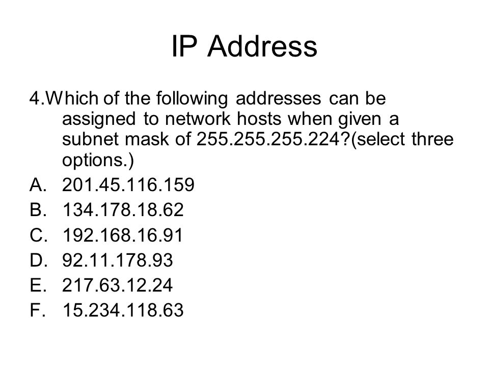
IP Address 4.Which of the following addresses can be assigned to network hosts when given a subnet mask of ?(select three options.)
26
IP Subnet-Zero

27
Classless Inter-Domain Routing

28
Variable Length Subnet Masks ( VLSM )
เครือข่ายที่เราใช้งานกันอยู่ไม่จำเป็นจะต้องมีขนาดเท่ากันเสมอไป เช่น LAN ต้องการ IP สำหรับอุปกรณ์มากกว่า 2 เครื่อง การเชื่อมต่อแบบจุดต่อจุด (Point-to-Point) ต้องการแค่ 2 IP ก็เพียงพอ VLSM จะยอมให้มีการแบ่ง Subnet ได้มากกว่า 1 ครั้งสำหรับแต่ละชุด IP เพื่อให้ได้ขนาด IP ตามที่ต้องการ VLSM จะช่วยลดจำนวนการจัดสรร IP ลง เป็นการใช้งาน IP อย่างมีประสิทธิภาพ VLSM ยังช่วยให้ Router ทำงานได้เร็วขึ้นเนื่องจากขนาดของ Routing Table เล็กลง
 ต้องการแค่ 2 IP ก็เพียงพอ. VLSM จะยอมให้มีการแบ่ง Subnet ได้มากกว่า 1 ครั้งสำหรับแต่ละชุด IP เพื่อให้ได้ขนาด IP ตามที่ต้องการ. VLSM จะช่วยลดจำนวนการจัดสรร IP ลง เป็นการใช้งาน IP อย่างมีประสิทธิภาพ. VLSM ยังช่วยให้ Router ทำงานได้เร็วขึ้นเนื่องจากขนาดของ Routing Table เล็กลง.")
29
Variable Length Subnet Masks ( VLSM )
")
30
Summarization Summarization, also called route aggregation, allows routing protocols to advertise many networks as one addres

31
Summarization

32
Cisco IOS Software EXEC Mode
There are two main EXEC modes for entering commands. Slide 1 of 2 Purpose: This slide describes the user EXEC mode. Emphasize: Present the operational aspects of user EXEC mode. Tell your students that this command level allows them to access only a limited amount of basic monitoring commands. Emphasize that they need to look carefully at the command prompter to make sure that they are in the appropriate mode for the command that they want to enter into the network device. If your class can remember this, this will eliminate (or at least reduce) the number of times that you have to point out that a lab step is failing because the student is in user mode rather than in enabled mode. Transition: An introduction of privileged (or enabled) mode.
 the number of times that you have to point out that a lab step is failing because the student is in user mode rather than in enabled mode. Transition: An introduction of privileged (or enabled) mode.")
33
Cisco IOS Software EXEC Mode (Cont.)
Slide 2 of 2 Purpose: This slide describes the privileged EXEC mode. Emphasize: As you present the introductory material on privileged (also called “enabled”) mode, emphasize that this mode is the entry mode for all other configuration modes. Tell your students that they will need this mode for ICND labs and most of the network administration that they do back on the job. Use the analogy of “the price of admission.” You must enter enable followed by the correct enable password; otherwise, you will not get into the network device; and will have to stay outside in user mode where you can only see a few basic things about the network device. Note: This slide ends the introductory material that is common to the network devices covered in ICND. Transition: Material specific to the initial startup of the Catalyst switch.
 mode, emphasize that this mode is the entry mode for all other configuration modes. Tell your students that they will need this mode for ICND labs and most of the network administration that they do back on the job. Use the analogy of the price of admission. You must enter enable followed by the correct enable password; otherwise, you will not get into the network device; and will have to stay outside in user mode where you can only see a few basic things about the network device. Note: This slide ends the introductory material that is common to the network devices covered in ICND. Transition: Material specific to the initial startup of the Catalyst switch.")
34
Overview of Router Modes
Emphasize: Here is a list of some of the configuration modes available. For a complete list of the router configuration modes, refer to the Cisco Documentation CD-ROM.

35
Saving Configurations
wg_ro_c# wg_ro_c#copy running-config startup-config Destination filename [startup-config]? Building configuration… Emphasize: Copying to NVRAM overwrites the contents in NVRAM. Copies the current configuration to NVRAM

36
Configuring Router Identification
Slide 2 of 2 Emphasize: Layer 2—The interface description command allows you to enter a one-line descriptive statement for each interface. This description is displayed in the output from the show interfaces command and appears in the show running-config and show startup-config listings. Sets the local identity or message for the accessed router or interface

37
Configuring a Router Password
Layer 2 of 2 Emphasize: The router has one enable password. Remember that this is your only protection. Whoever owns this password can do anything with the router, so be careful about communicating this password to others. To provide an additional layer of security, particularly for passwords that cross the network or are stored on a TFTP server, you can use either the enable password or enable secret commands. Both commands accomplish the same thing; that is, they allow you to establish an encrypted password that users must enter to access enable mode (the default), or any privilege level you specify. Cisco recommends that you use the enable secret command because it uses an improved encryption algorithm. Use the enable password command only if you boot an older image of the Cisco IOS software, or if you boot older boot ROMs that do not recognize the enable secret command. If you configure the enable secret password, it is used instead of the enable password, not in addition to it. Cisco supports password encryption. Turn on password encryption using the service password-encryption command. Then enter the desired passwords for encryption. Immediately, on the next line, enter the no service password-encryption command. Only those passwords that are set between the two commands will be encrypted. If you enter service password-encryption and then press Ctrl-Z to exit, all passwords will be encrypted. Note: Password recovery is not covered in the course materials. Refer the students to the IMCR class.
, or any privilege level you specify. Cisco recommends that you use the enable secret command because it uses an improved encryption algorithm. Use the enable password command only if you boot an older image of the Cisco IOS software, or if you boot older boot ROMs that do not recognize the enable secret command. If you configure the enable secret password, it is used instead of the enable password, not in addition to it. Cisco supports password encryption. Turn on password encryption using the service password-encryption command. Then enter the desired passwords for encryption. Immediately, on the next line, enter the no service password-encryption command. Only those passwords that are set between the two commands will be encrypted. If you enter service password-encryption and then press Ctrl-Z to exit, all passwords will be encrypted. Note: Password recovery is not covered in the course materials. Refer the students to the IMCR class.")
38
Other Console-Line Commands
Router(config)#line console 0 Router(config-line)#exec-timeout 0 0 Prevents console session timeout Router(config)#line console 0 Router(config-line)#logging synchronous Emphasize: If the student enters no exec by mistake, the console port EXEC mode will be disabled once the student is logged out of the current session. If this happens, you have to break into the router using ROM monitor to recover (set the config reg to 0x2142 so it will ignore NVRAM). Redisplays interrupted console input
#line console 0. Router(config-line)#exec-timeout 0 0. Prevents console session timeout. Router(config)#line console 0. Router(config-line)#logging synchronous. Emphasize: If the student enters no exec by mistake, the console port EXEC mode will be disabled once the student is logged out of the current session. If this happens, you have to break into the router using ROM monitor to recover (set the config reg to 0x2142 so it will ignore NVRAM). Redisplays interrupted console input.")
39
Configuring an Interface
Router(config)#interface type number Router(config-if)# type includes serial, ethernet, token ring, fddi, hssi, loopback, dialer, null, async, atm, bri, tunnel, and so on number is used to identify individual interfaces Router(config)#interface type slot/port Router(config-if)# Purpose: This slide shows the interface configuration mode. Emphasize: The top line is the format of the command used in fixed-port routers. The type field shows the interface type, which can be Ethernet, Token Ring, or another interface. The number field is the number of the interface. For example, if the router has two Ethernet interfaces, and one is known as Ethernet0, the other will be called Ethernet1. The second command is used on the Cisco 7000 and 7200 series routers, which can accept multiple interface cards with multiple ports on each card. In this case, the first number is the number of the card, or slot number. The second number is the port on the card. For example, on the second interface card, the first Ethernet interface is specified as Ethernet 2/0. If you have Cisco 7000 and 7500 series routers with VIP cards, you define an interface by slot, port adapters, and port numbers. Port adapters are assigned either a 0 or 1 number. Use the exit command to leave the current configuration mode. For modular routers, selects an interface Router(config-if)#exit Quits from current interface configuration mode
#interface type number. Router(config-if)# type includes serial, ethernet, token ring, fddi, hssi, loopback, dialer, null, async, atm, bri, tunnel, and so on. number is used to identify individual interfaces. Router(config)#interface type slot/port. Router(config-if)# Purpose: This slide shows the interface configuration mode. Emphasize: The top line is the format of the command used in fixed-port routers. The type field shows the interface type, which can be Ethernet, Token Ring, or another interface. The number field is the number of the interface. For example, if the router has two Ethernet interfaces, and one is known as Ethernet0, the other will be called Ethernet1. The second command is used on the Cisco 7000 and 7200 series routers, which can accept multiple interface cards with multiple ports on each card. In this case, the first number is the number of the card, or slot number. The second number is the port on the card. For example, on the second interface card, the first Ethernet interface is specified as Ethernet 2/0. If you have Cisco 7000 and 7500 series routers with VIP cards, you define an interface by slot, port adapters, and port numbers. Port adapters are assigned either a 0 or 1 number. Use the exit command to leave the current configuration mode. For modular routers, selects an interface. Router(config-if)#exit. Quits from current interface configuration mode.")
40
Configuring a Serial Interface
Enter Global Configuration Mode Router#configure terminal Router(config)# Router(config)#interface serial 0 Router(config-if)# Specify Interface Set Clock Rate (on DCE interfaces only) Router(config-if)#clock rate 64000 Router(config-if)# Layer 2 of 2 Purpose: This slide shows two configuration parameters for the serial interface. Emphasize: Layer 2— Issue the clock rate command with the desired speed. On serial links, one side of the link acts as the DCE and the other side of the link acts as the DTE. By default, Cisco routers are DTE devices, but can be configured as DCE devices. In a “back-to-back” cable configuration where a modem is not used, one end must provide the clocking signal. You must specify a clock rate for the DCE interface end in this type of environment. Desired clock rate is in bits per second. Be sure to enter the complete clock speed. For example, a clock rate of cannot be abbreviated to 56. If you are using an EIA/TIA-232 cable, using a high clock rate may cause errors on the line. Use the show controller serial 0 command to verify if the router has a DCE or DTE cable connected to it. Note, the router only reads the DCE/DTE cable information at startup. The bandwidth command overrides the default bandwidth (1.544M). The bandwidth parameter (in kbps) is used to calculate statistics like load and it is used by routing protocols such as IGRP. We will learn more about routing protocols in Chapter 9, “Determining IP Routes.” To return to privileged EXEC mode, enter exit until the privileged EXEC prompt appears. Note: In the lab, the core router has the DCE cables and the workgroup router has the DTE cable. Router(config-if)#bandwidth 64 Router(config-if)#exit Router(config)#exit Router# Set Bandwidth (recommended)
# Router(config)#interface serial 0. Router(config-if)# Specify Interface. Set Clock Rate (on DCE interfaces only) Router(config-if)#clock rate Router(config-if)# Layer 2 of 2. Purpose: This slide shows two configuration parameters for the serial interface. Emphasize: Layer 2— Issue the clock rate command with the desired speed. On serial links, one side of the link acts as the DCE and the other side of the link acts as the DTE. By default, Cisco routers are DTE devices, but can be configured as DCE devices. In a back-to-back cable configuration where a modem is not used, one end must provide the clocking signal. You must specify a clock rate for the DCE interface end in this type of environment. Desired clock rate is in bits per second. Be sure to enter the complete clock speed. For example, a clock rate of cannot be abbreviated to 56. If you are using an EIA/TIA-232 cable, using a high clock rate may cause errors on the line. Use the show controller serial 0 command to verify if the router has a DCE or DTE cable connected to it. Note, the router only reads the DCE/DTE cable information at startup. The bandwidth command overrides the default bandwidth (1.544M). The bandwidth parameter (in kbps) is used to calculate statistics like load and it is used by routing protocols such as IGRP. We will learn more about routing protocols in Chapter 9, Determining IP Routes. To return to privileged EXEC mode, enter exit until the privileged EXEC prompt appears. Note: In the lab, the core router has the DCE cables and the workgroup router has the DTE cable. Router(config-if)#bandwidth 64. Router(config-if)#exit. Router(config)#exit. Router# Set Bandwidth (recommended)")
41
Ethernet media-type Command
Router(config)#interface ethernet 2 Router(config-if)#media-type 10baset Selects the media-type connector for the Ethernet interface Purpose: This slide shows examples of the commands used to configure other types of interfaces. Note: The 2500 series router will auto-sense between the AUI or the 10BaseT port. Routers like the 4000 series router default to the AUI port and you have to use the media-type command to specify 10BaseT.
#interface ethernet 2. Router(config-if)#media-type 10baset. Selects the media-type connector for the Ethernet interface. Purpose: This slide shows examples of the commands used to configure other types of interfaces. Note: The 2500 series router will auto-sense between the AUI or the 10BaseT port. Routers like the 4000 series router default to the AUI port and you have to use the media-type command to specify 10BaseT.")
42
Disabling or Enabling an Interface
Router#configure terminal Router(config)#interface serial 0 Router(config-if)#shutdown %LINK-5-CHANGED: Interface Serial0, changed state to administratively down %LINEPROTO-5-UPDOWN: Line protocol on Interface Serial0, changed state to down Administratively turns off an interface Router#configure terminal Router(config)#interface serial 0 Router(config-if)#no shutdown %LINK-3-UPDOWN: Interface Seria0, changed state to up %LINEPROTO-5-UPDOWN: Line Protocol on Interface Serial0, changed state to up Emphasize: The Catalyst 1900 switch also uses the shut and no shut command. Enables an interface that is administratively shut down
#interface serial 0. Router(config-if)#shutdown. %LINK-5-CHANGED: Interface Serial0, changed state to administratively down. %LINEPROTO-5-UPDOWN: Line protocol on Interface Serial0, changed state to down. Administratively turns off an interface. Router#configure terminal. Router(config)#interface serial 0. Router(config-if)#no shutdown. %LINK-3-UPDOWN: Interface Seria0, changed state to up. %LINEPROTO-5-UPDOWN: Line Protocol on Interface Serial0, changed state to up. Emphasize: The Catalyst 1900 switch also uses the shut and no shut command. Enables an interface that is administratively shut down.")
43
Configuring the Router IP Address
wg_ro_c#configure terminal wg_ro_c(config)#interface ethernet 0 wg_ro_c(config-if)#ip address wg_ro_c(config-if)#no shutdown wg_ro_c(config-if)#exit
#interface ethernet 0. wg_ro_c(config-if)#ip address wg_ro_c(config-if)#no shutdown. wg_ro_c(config-if)#exit.")
44
Router show interfaces Command
Ethernet0 is up, line protocol is up Hardware is Lance, address is 00e0.1e5d.ae2f (bia 00e0.1e5d.ae2f) Internet address is /24 MTU 1500 bytes, BW Kbit, DLY 1000 usec, rely 255/255, load 1/255 Encapsulation ARPA, loopback not set, keepalive set (10 sec) ARP type: ARPA, ARP Timeout 04:00:00 Last input 00:00:07, output 00:00:08, output hang never Last clearing of "show interface" counters never Queueing strategy: fifo Output queue 0/40, 0 drops; input queue 0/75, 0 drops 5 minute input rate 0 bits/sec, 0 packets/sec 5 minute output rate 0 bits/sec, 0 packets/sec 81833 packets input, bytes, 0 no buffer Received broadcasts, 0 runts, 0 giants, 0 throttles 1 input errors, 0 CRC, 0 frame, 0 overrun, 1 ignored, 0 abort 0 input packets with dribble condition detected 55794 packets output, bytes, 0 underruns 0 output errors, 0 collisions, 1 interface resets 0 babbles, 0 late collision, 4 deferred 0 lost carrier, 0 no carrier 0 output buffer failures, 0 output buffers swapped out Purpose: This slide presents the show interfaces command, which indicates whether the network is operating at the physical and data link layers. The command output is interpreted later in this chapter. Emphasize: The top line of the output tells us that the line is up. A few lines down, the output provides the IP address, and below that some characteristics like BW for bandwidth, and DLY for delay. On the next line down, we find an encapsulation type of ARPA. ARPA means Ethernet II, which is the default IP encapsulation type for Ethernet interfaces on Cisco routers. A runt is an Ethernet frame that is too small to be legal (less than 64 bytes), and a giant is an Ethernet frame that is too big (greater than 1518 bytes).
 Internet address is /24. MTU 1500 bytes, BW Kbit, DLY 1000 usec, rely 255/255, load 1/255. Encapsulation ARPA, loopback not set, keepalive set (10 sec) ARP type: ARPA, ARP Timeout 04:00:00. Last input 00:00:07, output 00:00:08, output hang never. Last clearing of show interface counters never. Queueing strategy: fifo. Output queue 0/40, 0 drops; input queue 0/75, 0 drops. 5 minute input rate 0 bits/sec, 0 packets/sec. 5 minute output rate 0 bits/sec, 0 packets/sec packets input, bytes, 0 no buffer. Received broadcasts, 0 runts, 0 giants, 0 throttles. 1 input errors, 0 CRC, 0 frame, 0 overrun, 1 ignored, 0 abort. 0 input packets with dribble condition detected packets output, bytes, 0 underruns. 0 output errors, 0 collisions, 1 interface resets. 0 babbles, 0 late collision, 4 deferred. 0 lost carrier, 0 no carrier. 0 output buffer failures, 0 output buffers swapped out. Purpose: This slide presents the show interfaces command, which indicates whether the network is operating at the physical and data link layers. The command output is interpreted later in this chapter. Emphasize: The top line of the output tells us that the line is up. A few lines down, the output provides the IP address, and below that some characteristics like BW for bandwidth, and DLY for delay. On the next line down, we find an encapsulation type of ARPA. ARPA means Ethernet II, which is the default IP encapsulation type for Ethernet interfaces on Cisco routers. A runt is an Ethernet frame that is too small to be legal (less than 64 bytes), and a giant is an Ethernet frame that is too big (greater than 1518 bytes).")
45
Interpreting the Interface Status
Purpose: This slide explains how to interpret the show interfaces serial command output. Emphasize: The show interfaces serial command output indicates that the serial interface is up and the line protocol is up. The first parameter refers to the hardware layer and essentially reflects whether the interface is receiving the Carrier Detect signal from the other end. The second parameter refers to the data link layer. This parameter reflects whether the data link layer protocol keepalives are being received. If both the interface and the line protocol are up, the connection is operational. If the hardware is up and the line protocol is down, a connection problem exist such as no clocking, wrong encapsulation type, or no keepalives. If both the line protocol and the interface are down, a cable might never have been attached to the router. On the serial cable, you can plug in the cable upside-down, causing the pins on the serial cable to break. There is one more possibility. If the information says “administratively down,” you have manually disabled (shut) the interface. Cisco offers a hardware class (IMCR) that discusses the router hardware in more detail.
 the interface. Cisco offers a hardware class (IMCR) that discusses the router hardware in more detail.")
46
Verifying a Serial Interface Configuration
Router#show interface serial 0 Serial0 is up, line protocol is up Hardware is HD64570 Internet address is /24 MTU 1500 bytes, BW 64 Kbit, DLY usec, rely 255/255, load 1/255 Encapsulation HDLC, loopback not set, keepalive set (10 sec) Last input 00:00:09, output 00:00:04, output hang never Last clearing of "show interface" counters never Input queue: 0/75/0 (size/max/drops); Total output drops: 0 Queueing strategy: weighted fair Output queue: 0/1000/64/0 (size/max total/threshold/drops) Conversations 0/1/256 (active/max active/max total) Reserved Conversations 0/0 (allocated/max allocated) 5 minute input rate 0 bits/sec, 0 packets/sec 5 minute output rate 0 bits/sec, 0 packets/sec (output omitted) BW 64 Kbit, Purpose: This slide shows how to verify the changes you make to an interface. Emphasize: Notice the bandwidth has been changed to 64K from the default of 1.544M.
 Last input 00:00:09, output 00:00:04, output hang never. Last clearing of show interface counters never. Input queue: 0/75/0 (size/max/drops); Total output drops: 0. Queueing strategy: weighted fair. Output queue: 0/1000/64/0 (size/max total/threshold/drops) Conversations 0/1/256 (active/max active/max total) Reserved Conversations 0/0 (allocated/max allocated) 5 minute input rate 0 bits/sec, 0 packets/sec. 5 minute output rate 0 bits/sec, 0 packets/sec. (output omitted) BW 64 Kbit, Purpose: This slide shows how to verify the changes you make to an interface. Emphasize: Notice the bandwidth has been changed to 64K from the default of 1.544M.")
47
Serial Interface show controller Command
Router#show controller serial 0 HD unit 0, idb = 0x121C04, driver structure at 0x127078 buffer size HD unit 0, V.35 DTE cable . V.35 DTE Cable Emphasize: This command requires a space between the word serial and the interface number. The router only checks for the cable type at powerup. Shows the cable type of serial cables

48
Config DHCP

49
Setting Secure Shell (SSH)
")
50
Setting Secure Shell (SSH)
")
51
Doing the do Command

52
Using the Pipe

53
Cisco’s Security Device Manager

54
Cisco’s Security Device Manager
Now we can consider another industry first from Cisco. We were the first to market with an Intrusion Prevention System, or IPS, in a router, providing an inline ability to mitigate network attacks by dropping attack packets. Cisco IPS can be used it for combating worms and viruses in real time, utilizing the signature database of Cisco IDS Sensors; a wide range of attack and worm signatures are already available – over 740 and growing! And note that the signature names and numbers are identical to those in Cisco IDS appliances, making management and administration easier. And with Cisco SDM, you have a powerful and flexible GUI to manage signatures and actions. Having IPS built into the router gives Cisco a significant competitive advantage. Visibility and control of the network is expanded without having to add a separate device, with all the associated management and support costs. IPS can be used where it may previously have been uneconomic to deploy a dedicated IDS sensor to mitigate the impact of worms, viruses and trojans.

55
Cisco’s Security Device Manager
Now let’s look at Threat Defence. The Cisco IOS Firewall integrates robust firewall functionality and intrusion prevention for every network perimeter. It is an uncompromising Enterprise class EAL 4-certified firewall that enables scalable deployment to meet the bandwidth and performance requirements of the branch office, typically in the 125 Mbps to 1.1Gbps range. In many ways, the Cisco IOS Firewall is superior to Firewall appliances. It adds greater depth and flexibility to existing Cisco IOS security solutions, such as authentication, encryption, and failover, by delivering state-of-the-art security features: stateful packet inspection of IPv4 and IPv6, application-based filtering, protocol anomaly detection, dynamic per-user authentication and authorization, VRF aware, URL Filtering and others. The Transparent Firewall function allows customers to deploy a Firewall without making address changes. In addition, when it is combined with Cisco IOS IPsec and Cisco IOS Technologies, such as L2TP tunneling and Quality of Service (QoS), Cisco IOS Firewall provides a complete, integrated virtual private network (VPN) solution. Remember, this is a real Firewall: it is ICSA certified and has an easy GUI for managing the policy table.
, Cisco IOS Firewall provides a complete, integrated virtual private network (VPN) solution. Remember, this is a real Firewall: it is ICSA certified and has an easy GUI for managing the policy table.")
56
Managing a cisco internetwork
เปรียบเหมือน windows (OS) เปรียบเหมือน hard disk Flash NVRAM RAM เก็บ IOS เก็บ config เก็บ config แต่ยังไม่ save ROM เปรียบเหมือน Bios บน PC
 เปรียบเหมือน hard disk. Flash. NVRAM. RAM. เก็บ IOS. เก็บ config. เก็บ config แต่ยังไม่ save. ROM. เปรียบเหมือน Bios บน PC.")
57
Router Power-On/Bootup Sequence
Perform power-on self test (POST). Load and run bootstrap code. Find the Cisco IOS software. Load the Cisco IOS software. Find the configuration. Load the configuration. Run the configured Cisco IOS software. Emphasize: In a later slide, there is a very detailed flowchart of the router startup process.
. Load and run bootstrap code. Find the Cisco IOS software. Load the Cisco IOS software. Find the configuration. Load the configuration. Run the configured Cisco IOS software. Emphasize: In a later slide, there is a very detailed flowchart of the router startup process.")
58
Finding the Cisco IOS Software
Note: There is a detailed flowchart of the router startup process on the next slide.

59
Loading the Cisco IOS Software from Flash Memory
Note: The 2500 series routers do not operate this way. The 2500 series routers normally run Cisco IOS from Flash. The Cisco IOS in Flash is not compressed but it is relocatable. Relocatable means the Cisco IOS image can be run from Flash or from RAM. The 2500 can run from RAM if you use the boot system tftp command to boot the Cisco IOS image. The Rxboot mode is also run from RAM on the 2500 routers. The flash memory file is decompressed into RAM.

60
Loading the Configuration
Emphasize: Using the default config register value (0x2102), the router will load the config from NVRAM at startup. Load and execute the configuration from NVRAM. If no configuration is present in NVRAM, enter setup mode.
, the router will load the config from NVRAM at startup. Load and execute the configuration from NVRAM. If no configuration is present in NVRAM, enter setup mode.")
61
Determining the Current Configuration Register Value
wg_ro_a#show version Cisco Internetwork Operating System Software IOS (tm) 2500 Software (C2500-JS-L), Version 12.0(3), RELEASE SOFTWARE (fc1) Copyright (c) by cisco Systems, Inc. Compiled Mon 08-Feb-99 18:18 by phanguye Image text-base: 0x03050C84, data-base: 0x ROM: System Bootstrap, Version 11.0(10c), SOFTWARE BOOTFLASH: 3000 Bootstrap Software (IGS-BOOT-R), Version 11.0(10c), RELEASE SOFTWARE (fc1) wg_ro_a uptime is 20 minutes System restarted by reload System image file is "flash:c2500-js-l_120-3.bin" --More-- Configuration register is 0x2102 Emphasize: Use the show version command to display the value of the config register setting. When you change the config register, you will see the change from the show version output: Configuration register is 0x2102 (will be 0x2142 at next reload). The new config register value will be used at the next reload. Configuration register value in show version
 2500 Software (C2500-JS-L), Version 12.0(3), RELEASE SOFTWARE (fc1) Copyright (c) by cisco Systems, Inc. Compiled Mon 08-Feb-99 18:18 by phanguye. Image text-base: 0x03050C84, data-base: 0x ROM: System Bootstrap, Version 11.0(10c), SOFTWARE. BOOTFLASH: 3000 Bootstrap Software (IGS-BOOT-R), Version 11.0(10c), RELEASE SOFTWARE (fc1) wg_ro_a uptime is 20 minutes. System restarted by reload. System image file is flash:c2500-js-l_120-3.bin --More-- Configuration register is 0x2102. Emphasize: Use the show version command to display the value of the config register setting. When you change the config register, you will see the change from the show version output: Configuration register is 0x2102 (will be 0x2142 at next reload). The new config register value will be used at the next reload. Configuration register value in show version.")
62
Configuration Register Values
Configuration register bits 3, 2, 1, and 0 set boot option. Check the configuration register value with show version. Layer 4 of 4 Emphasize: Layer 4—Finishes with the third case, a boot field setting in the range of 0x2 to 0xF. The entry of a configuration register value in the 0x2 to 0xF range is significant. When the router attempts to boot from the net (Netboot), the bootstrap program generates a Cisco IOS filename based on the value of the boot field. For example, with the setting 0x2, the default Cisco IOS filename generated will be cisco2-xxxx, where xxxx refers to a processor name (for example, 2500). Again, refer students to the IMCR course for details. You use the config-register command to change the value. Notice that the bottom lines of the show version output indicates what value the config register will be on the next reload.
, the bootstrap program generates a Cisco IOS filename based on the value of the boot field. For example, with the setting 0x2, the default Cisco IOS filename generated will be cisco2-xxxx, where xxxx refers to a processor name (for example, 2500). Again, refer students to the IMCR course for details. You use the config-register command to change the value. Notice that the bottom lines of the show version output indicates what value the config register will be on the next reload.")
63
Configuration Register Values
รหัสของ bootstrap ทั่วไป 0x2102 มีได้ 3 ค่า คือ 0 = Rommon [>] 1 = Rx-boot [router(boot)] 2 = IOS [router>] เอามาเขียนเป็นเลขฐานสอง 0 0 = 9600 0 1 = 4800 1 0 = 2400 1 1 = 1200 มีได้ 2 ค่าคือ 0 = load config จาก NVRAM 4 = skip การ load config
] 2 = IOS [router>] เอามาเขียนเป็นเลขฐานสอง = = = = มีได้ 2 ค่าคือ. 0 = load config จาก NVRAM. 4 = skip การ load config.")
64
Password Recovery

65
show version Command Router#show version Cisco Internetwork Operating System Software IOS (tm) C2600 Software (C2600-JS-M), Version 12.0(7a), RELEASE SOFTWARE (fc1) Copyright (c) by cisco Systems, Inc. Compiled Tue 05-Feb-02 01:48 by pwade Image text-base: 0x , data-base: 0x80B0404C ROM: System Bootstrap, Version 11.3(2)XA4, RELEASE SOFTWARE (fc1) Router uptime is 1 minute System restarted by reload System image file is "flash:c2600-js-mz.120-7a.bin" cisco 2610 (MPC860) processor (revision 0x300) with 53248K/12288K bytes of memory. Processor board ID JAD06090BMD ( ) M860 processor: part number 0, mask 49 Bridging software. X.25 software, Version SuperLAT software (copyright 1990 by Meridian Technology Corp). TN3270 Emulation software. Basic Rate ISDN software, Version 1.1. 1 Ethernet/IEEE interface(s) 2 Serial(sync/async) network interface(s) 1 ISDN Basic Rate interface(s) 32K bytes of non-volatile configuration memory. 16384K bytes of processor board System flash (Read/Write) Configuration register is 0x2102 Note: The current state of the Flash memory is in read-only mode. It is running Cisco IOS from Flash. This router has a total of 16 MB of Flash memory. The Flash contains one Cisco IOS image and there is 6.69 MB of available space left in Flash.
 C2600 Software (C2600-JS-M), Version 12.0(7a), RELEASE SOFTWARE (fc1) Copyright (c) by cisco Systems, Inc. Compiled Tue 05-Feb-02 01:48 by pwade. Image text-base: 0x , data-base: 0x80B0404C. ROM: System Bootstrap, Version 11.3(2)XA4, RELEASE SOFTWARE (fc1) Router uptime is 1 minute. System restarted by reload. System image file is flash:c2600-js-mz.120-7a.bin cisco 2610 (MPC860) processor (revision 0x300) with 53248K/12288K bytes of memory. Processor board ID JAD06090BMD ( ) M860 processor: part number 0, mask 49. Bridging software. X.25 software, Version SuperLAT software (copyright 1990 by Meridian Technology Corp). TN3270 Emulation software. Basic Rate ISDN software, Version Ethernet/IEEE interface(s) 2 Serial(sync/async) network interface(s) 1 ISDN Basic Rate interface(s) 32K bytes of non-volatile configuration memory K bytes of processor board System flash (Read/Write) Configuration register is 0x2102. Note: The current state of the Flash memory is in read-only mode. It is running Cisco IOS from Flash. This router has a total of 16 MB of Flash memory. The Flash contains one Cisco IOS image and there is 6.69 MB of available space left in Flash.")
66
show flash Command wg_ro_a#show flash System flash directory: File Length Name/status c2500-js-l_120-3.bin [ bytes used, available, total] 16384K bytes of processor board System flash (Read ONLY) Note: The current state of the Flash memory is in read-only mode. It is running Cisco IOS from Flash. This router has a total of 16 MB of Flash memory. The Flash contains one Cisco IOS image and there is 6.69 MB of available space left in Flash.
 Note: The current state of the Flash memory is in read-only mode. It is running Cisco IOS from Flash. This router has a total of 16 MB of Flash memory. The Flash contains one Cisco IOS image and there is 6.69 MB of available space left in Flash.")
งานนำเสนอที่คล้ายกัน
 ในช่วงยุค Internet เพิ่ง เริ่มต้น เป็นบริษัทที่ดำเนินงานทางด้าน.>")
 2007 Pearson Education, Inc. All rights reserved. 0-13-222158-61 Java Programming Language.>")
![คำสั่ง DISPLAY รูปแบบที่ 1 DISPLAY identifier-1, identifier-2 … literal-1 literal-2 [ UPON mnemonic-name ] ตัวอย่าง DISPLAY STUDENT-NAME. DISPLAY.](/7/1925791/big_thumb.jpg "คำสั่ง DISPLAY รูปแบบที่ 1 DISPLAY identifier-1, identifier-2 … literal-1 literal-2 [ UPON mnemonic-name ] ตัวอย่าง DISPLAY STUDENT-NAME. DISPLAY.>")


>")


>")