ดาวน์โหลดงานนำเสนอ
1
ขั้นตอนการแปลงไฟล์

2
การเขียนโปรแกรมภาษา Assembly
Object File : จะเป็นไฟล์ที่มี นามสกุล .OBJ ซึ่งจะประกอบด้วยภาษาเครื่องที่ ใช้สำหรับแปลงเป็น .EXE (Executable File) โดยโปรแกรม Link List File : เป็นไฟล์ที่มีนามสกุล .LST จะบรรจุภาษาเครื่อง และโปรแกรม อธิบายข้อผิดพลาด ที่เกิดขึ้น(error)เพื่อให้เราสามารถ แก้ไข้ผิดพลาดได้ง่าย Cross-Reference File : เป็นไฟล์ที่ นามสกุล .CRF จะรวบรวมชื่อต่างๆที่ใช้ โปรแกรมทั้งหมด LINK จะทำการแปลง ไฟล์รหัสภาษาเครื่อง (Object File) เป็น Executable File จากนั้นจะได้ ไฟล์ใหม่ 2 ไฟล์ - Run File : เป็นไฟล์ที่มีนามสกุล .EXE ซึ่งสามารถโหลดลงหน่วยความจำ
 โดยโปรแกรม Link. List File : เป็นไฟล์ที่มีนามสกุล .LST จะบรรจุภาษาเครื่อง และโปรแกรม อธิบายข้อผิดพลาด ที่เกิดขึ้น(error)เพื่อให้เราสามารถ แก้ไข้ผิดพลาดได้ง่าย. Cross-Reference File : เป็นไฟล์ที่ นามสกุล .CRF จะรวบรวมชื่อต่างๆที่ใช้ โปรแกรมทั้งหมด LINK จะทำการแปลง ไฟล์รหัสภาษาเครื่อง (Object File) เป็น Executable File จากนั้นจะได้ ไฟล์ใหม่ 2 ไฟล์ - Run File : เป็นไฟล์ที่มีนามสกุล .EXE ซึ่งสามารถโหลดลงหน่วยความจำ.")
3
การ complie ในภาษา Assembly
ในที่นี้ใน Turbo Assembly ในการทำงานจะต้องมีการพิมพ์ โปรแกรม ด้วยตัวช่วยพิมพ์ (Editor) บันทึกให้เป็น นามสกุล . ASM ก่อน ตัวอย่าง Editor ที่ ทำการใช้งาน เช่น Qedit , EditPlus ,NotePad, MsWord หรืออื่นๆ จะได้ Object filename object filename [ ชื่อแฟ้มที่ complie .object] : เป็นแฟ้ม .Obj Source listing [ NUL.LST ]: เป็น listing File Cross reference [ NUL . CRF ] : “NUL” ก็คือ (NO File ) ค่าซึ่งอยู่ใน [ … ] คือ “Default value” หากไม่มีข้อผิดพลาดเกิดขึ้นจะได้ Warning Severe Errors Errors หากมีข้อผิดพลาดเกิดขึ้นต้องกลับไปแก้ไขก่อนที่จะทำการ Link โปรแกรม ( .Obj) โดยใช้ Tlink ชื่อแฟ้ม ซึ่งแฟ้มนามสกุล .Obj จากนั้น จะได้แฟ้ม .EXE สามารถเรียกใช้งานได้ TASM ชื่อแฟ้ม ที่เขียนด้วย Editor.ASM
 บันทึกให้เป็น นามสกุล . ASM ก่อน. ตัวอย่าง Editor ที่ ทำการใช้งาน เช่น Qedit , EditPlus ,NotePad, MsWord หรืออื่นๆ. จะได้ Object filename. object filename [ ชื่อแฟ้มที่ complie .object] : เป็นแฟ้ม .Obj. Source listing [ NUL.LST ]: เป็น listing File. Cross reference [ NUL . CRF ] : NUL ก็คือ (NO File ) ค่าซึ่งอยู่ใน [ … ] คือ Default value หากไม่มีข้อผิดพลาดเกิดขึ้นจะได้ Warning Severe. Errors Errors. หากมีข้อผิดพลาดเกิดขึ้นต้องกลับไปแก้ไขก่อนที่จะทำการ Link โปรแกรม ( .Obj) โดยใช้ Tlink ชื่อแฟ้ม ซึ่งแฟ้มนามสกุล .Obj จากนั้น จะได้แฟ้ม .EXE สามารถเรียกใช้งานได้ TASM ชื่อแฟ้ม ที่เขียนด้วย Editor.ASM.")
4
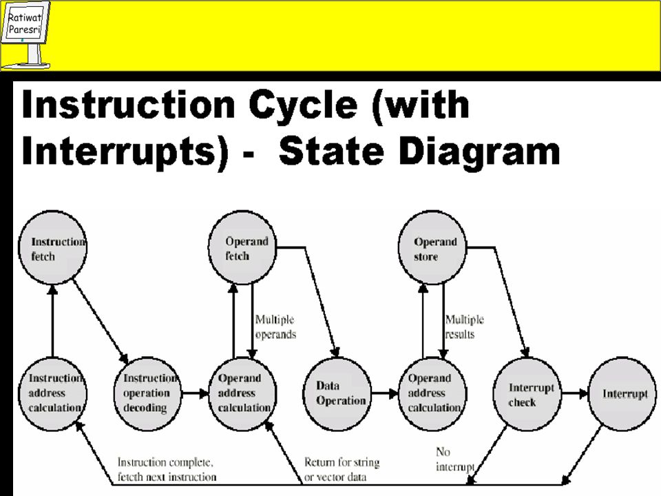
Instruction Cycle Two steps: Fetch Execute

5
Fetch Cycle Program Counter (PC) holds address of next instruction to fetch Processor fetches instruction from memory location pointed to by PC Increment PC Unless told otherwise Instruction loaded into Instruction Register (IR) Processor interprets instruction and performs required actions
 Processor interprets instruction and performs required actions.")
6
Execute Cycle Processor-memory Processor I/O Data processing Control
data transfer between CPU and main memory Processor I/O Data transfer between CPU and I/O module Data processing Some arithmetic or logical operation on data Control Alteration of sequence of operations e.g. jump Combination of above

8
Bus Interconnection Schema

9
Traditional (ISA) (with cache)
 (with cache)")
10
High performance speed Bus

11
Cache Small amount of fast memory
Sits between normal main memory and CPU May be located on CPU chip or module

12
Typical Cache Organization

13
I/O Module Diagram

14
Arithmetic & Logic Unit
Does the calculations Everything else in the computer is there to service this unit Handles integers May handle floating point (real) numbers May be separate FPU (maths co-processor) May be on chip separate FPU (486DX +)
 numbers. May be separate FPU (maths co-processor) May be on chip separate FPU (486DX +)")
15
ALU Inputs and Outputs

16
Addressing Modes Immediate Direct Indirect Register Register Indirect
Displacement (Indexed) Stack
 Stack.")
17
Addressing Diagram Immediate Instruction Opcode Operand Instruction
Address A Opcode Memory Operand

18
Control Unit

20
Basic Elements of Processor
ALU Registers Internal data pahs External data paths Control Unit


.>")
>")


