ดาวน์โหลดงานนำเสนอ
1
กลุ่มที่ 4 ROCK BOLTS สมาชิกในกลุ่ม 1 นายชัชชัย หนูเจริญ
กลุ่มที่ 4 ROCK BOLTS สมาชิกในกลุ่ม 1 นายชัชชัย หนูเจริญ 2 นายทรงพล มงคลพันธุ์ 3 นายมนัส จันทร์วิไล 4 นายวิทูรย์ จั่นเพ็ชร์ 5 นายอดิเรก รักชุม 6 นายอรรถวีร์ มิลินทางกูร

2
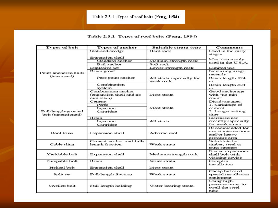
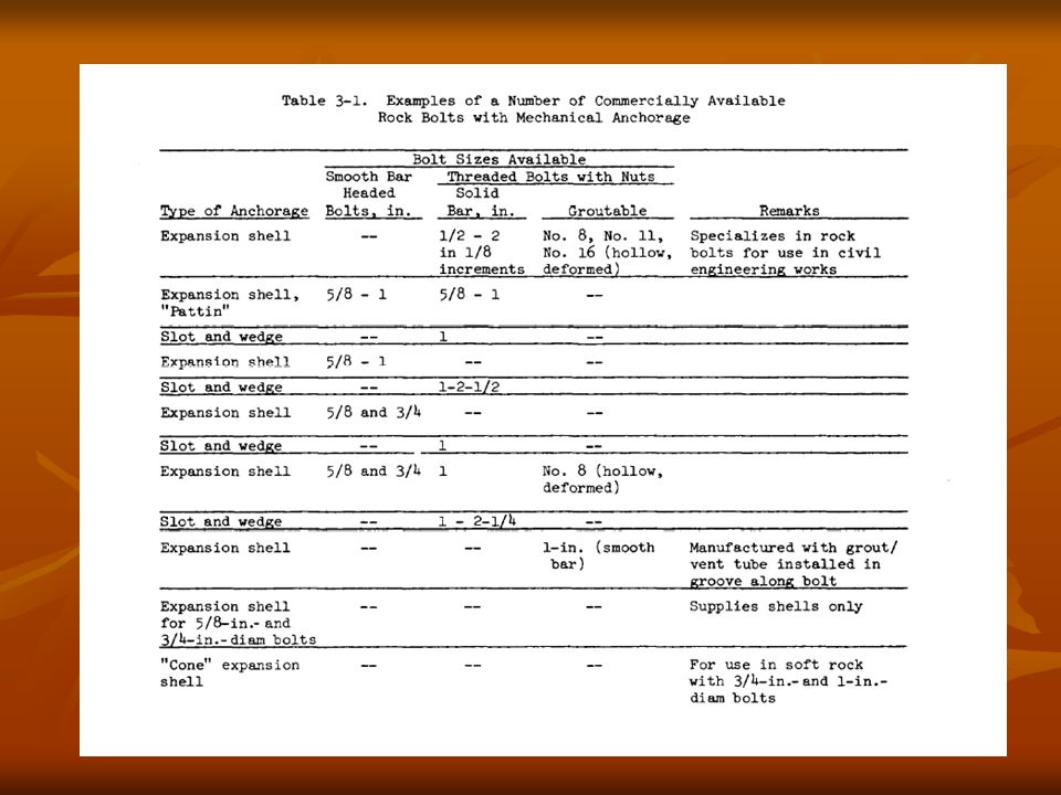
Type of Anchored Rockbolt
Figures to show the hierarchical architectures for trouble-shooting bolting systems.

3
1. Mechanical Bolts

4
Slot & Wedge Anchor Rockbolt
Advantages : - Inexpensive - Simple - Immediate tensioning Disadvantages : - Small contact area - Local crushing - Unreliability in poor rock Applications : - Rarely used today

5
Mechanically Anchored Rockbolt

6
2. FullyGroutBolts

7
Cement Grouted Rockbolt
Advantages : - Inexpensive - Simple Disadvantages : - Can’t be tensioned Applications : - Light support, mining - Pipework, ventilation tube in civil eng.

8
3. TensionRebarBolts

9
Split-set Dowel Advantages : Disadvantages : Applications :
- Quick to install - Simple - Cheaper than Cement Grouted Rockbolt Disadvantages : - Can’t be tensioned - Rusting - Can’t be grouted Applications : - Light support - Short-term support

10
Swellex Dowel Advantages : Disadvantages : Applications :
- High anchorage load - Simple - Inexpensive - Small axial force Disadvantages : - Can’t be grouted - Strength up to tube Applications : - Medium-term reinf. in mining

11
Expansion Shell Anchor
Advantages : - High bolt load - Very reliable - Immediate tensioning Disadvantages : - Expensive - Required skill and supervision Applications : - Permanent support for civil eng. - Non-grout use in mining

12
4. Combinepointbolts

13
5. MResinBolts

14
Resin Grouted Rockbolt
Advantages : - Convenient - Simple - Very high str. anchor Disadvantages : - Expensive - Limited shelf-life Applications : - Which cost is less than speed & reliability

15
Resin Grouted Rockbolt

16
Accessories-Face Plates

17
Accessories-Wire Mesh

18
Accessories-Shortcrete

20
Main Propose Anchored Rockbolt
II Adhesion Friction Resin High contact load Cement Low contact load Expansion of bolt Compression of bolt

21
การใช้สลักหินในการค้ำยันจะทำให้เกิดผลดังนี้
1. ทำให้เกิดโซนของแรงกดในแนวรัศมีโดยรอบในหิน ซึ่งเกิดจากแรง ดึงในสลักยึดหิน 2. การยึดของสลักหิน เป็นสาเหตุให้เกิดหน่วยแรงกดสัมผัสกระทำตั้งฉากกับทิศทางของสลักหิน และเกิดขึ้นโดยการกระทำร่วมกันของแรงดึงในสลักยึดหิน และปฏิกิริยาตอบสนองของหินต่อการยึด 3. หน่วยแรงกดโดยแรงที่เกิดขึ้นจากแรงดึงในสลักหินทำให้เกิดแรงกดดันเข้าไปและมีการขยายตัวตามแนวนอน ซึ่งผลจากการตรึงนี้ทำให้การกดถูกเหนี่ยวนำให้เกิดขึ้นเป็นมุมฉากกับทิศทางของสลักยึดหิน 4. การแปรแปรเปลี่ยนหรือการเปลี่ยนรูปของผิวที่ถูกขุด เนื่องจากการปรับหน่วยแรงโดยรอบของอุโมงค์จะไม่ขยายขอบเขตออกไปและไม่เคลื่อนที่เข้าสู่อุโมงค์ โดยการใส่สลักหินเข้าไปเป็นชุด

22
แผนผังการทำงาน 1. ก่อนการขุดเจาะ (Before Excavation)
สำรวจบริเวณที่จะทำการขุดเจาะ เครื่องมือขุดเจาะที่ต้องการใช้ ประวัติของสถานที่จากบริเวณใกล้เคียง เลือกวิธีการใช้ Rockbolts การออกแบบขั้นต้น เลือกวีธีการติดตามประเมินผล

23
2. ระหว่างการขุดเจาะ (During Excavation)
การสำรวจรายละเอียดของบริเวณที่จะขุดเจาะ การติดตั้ง Rockbolts การติดตั้งระบบการติดตามประเมินผล พิจารณาทบทวนการออกแบบ พิจารณาออกแบบใหม่ 3. หลังการขุดเจาะ (After Excavation) บันทึกและติดตามประเมินผล
 บันทึกและติดตามประเมินผล.")
24
การออกแบบ Rock bolts ข้อสังเกตที่เกี่ยวกับขนาดของสลักยึด
1. ขนาดและความยาวจะขึ้นอยู่กับสภาพของหิน 2. ความยาวของสลักยึดต้องมีค่าอย่างน้อยเท่ากับความหนาของโครงสร้างหินโค้งที่ทำหน้าที่รับแรงโดยรอบอุโมงค์ รวมกับระยะทางเฉลี่ยระหว่างสลักยึดที่อยู่ข้างเคียง 3. ระยะห่างของสลักยึดควรให้เท่ากัน

25
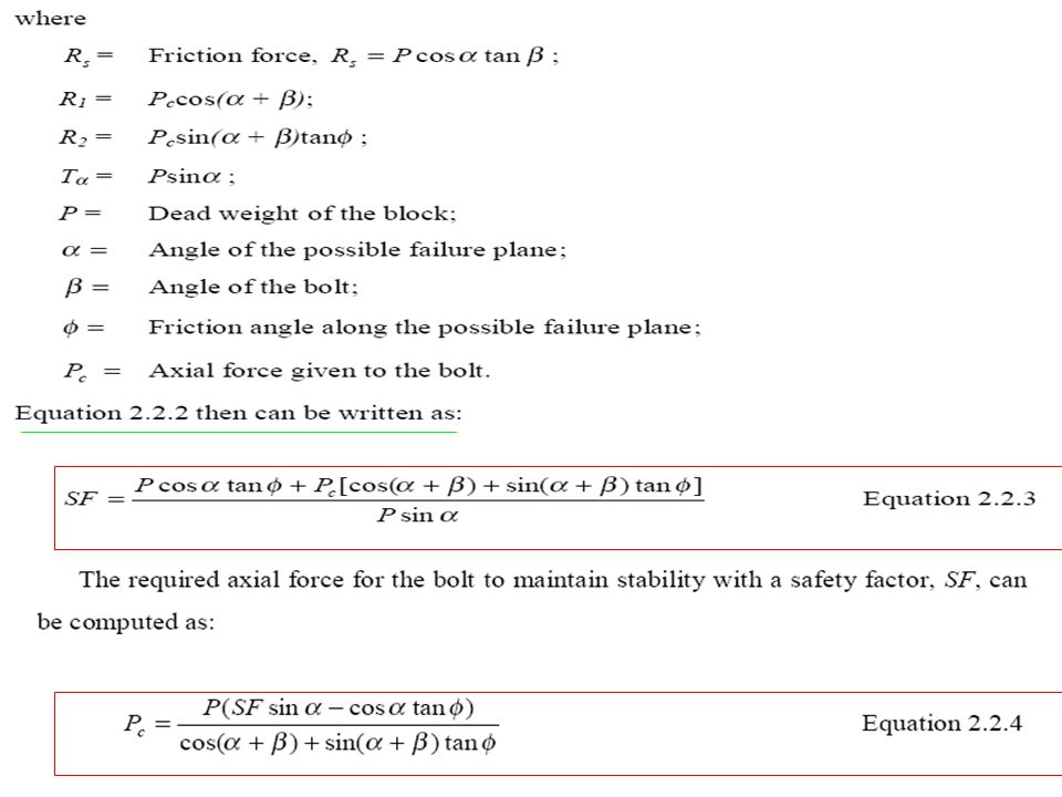
1.Stability of bolted block
Safety Factor SF is required, then (Biron and Arioglu, 1983):
:")
27
Calculate factor of safety (FS)
")
28
Calculate factor of safety (FS) of the unreinforced slope using equation (1) below to determine the need for rock bolts 1. The F.S should be calculated for both the wet and dry conditions 2. Decide upon the minimum FS necessary to insure slope stability 3. Calculate the total rock bolt force T (equation 2) 4. The rock bolt lengths should, in general, be determined such that when using the design bolt spacing, the force cone generated from the bottom of the anchor overlaps
 4. The rock bolt lengths should, in general, be determined such that when using the design bolt spacing, the force cone generated from the bottom of the anchor overlaps.")
29
6 = angle of rock bolt with horizontal; bolt sloping up above
where W = weight of rock 6 = angle of rock bolt with horizontal; bolt sloping up above horizontal is of a negative angle c1 = angle of discontinuity to the horizontal E = angle of resultant force due to earthquake or blasting forces and W c = cohesion of rock H = vertical distance from point where discontinuity daylights on slope to top of slope u = groundwater force T = total force due to rock anchors Equation (1) was selected for the calculation of the FS since the equation contains most of the parameters required for slope-stability analysis and is straightforward to use. To determine the optimum direction of the rock bolts, equation (1) is differentiated with respect to 6 . This gives a maximum FS when
 was selected for the calculation of the FS since the equation contains most of the parameters required for slope-stability analysis and is straightforward to use. To determine the optimum direction of the rock bolts, equation (1) is differentiated with respect to 6 . This gives a maximum FS when.")
30
2. Length of bolt

31
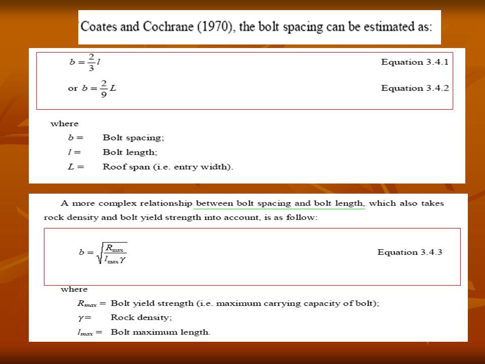
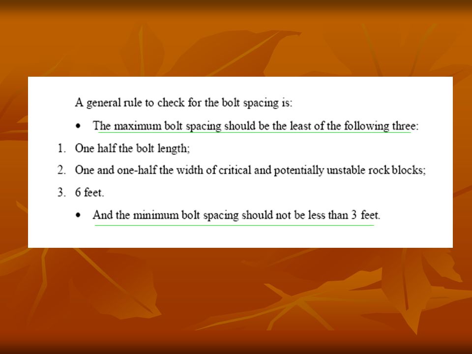
3. Pattern and spacing

34
4. Bolt diameter

35
การวิเคราะห์ความมั่นคงของโครงสร้างหิน
1. การวิเคราะห์ความมั่นคงของมวลก้อนหิน 1.1 ค้ำยันมวลก้อนหินที่มีโอกาสตกลงมา 1.2 ค้ำยันมวลก้อนหินที่มีโอกาสเลื่อนหลุดลงมา 2. วิเคราะห์โดยใช้แนวคิดของคานและพื้นใช้กับแนวการทับถมของหิน 2.1 ใช้เป็นส่วนรั้งแนวการทับถมของหินเหนืออุโมงค์ 2.2 การสร้างแนวทับถมเหนืออุโมงค์ให้แข็งแรงขึ้น 3. วิเคราะห์โดยใช้แนวคิดการส่งถ่ายแรงตามแนวโค้ง

36
ค้ำยันมวลก้อนหินที่มีโอกาสตกลงมา
N = จำนวนสมอยึด W = น้ำหนักของหินที่มีโอกาสตกลงมาได้ f = ตัวคูณค่าความปลอดภัย B = load bearing capacity of bolt

37
ค้ำยันมวลก้อนหินที่มีโอกาสเลื่อนหลุดลงมา
b = มุมเอียงรอยแตกของหินทำกับแนวราบ f = มุมเสียดทานของหินตรงรอยแตก C = cohesive strength of sliding A = พื้นหินที่ติดกับรอยเลื่อน a = มุมที่ทำกับเส้นแนวตั้งฉากของรอยแตกหินกับสมอยึด

38
ใช้เป็นส่วนรั้งแนวการทับถมของหินเหนืออุโมงค์
W = f*S*C*h*r h = ความหนาของหินที่ไม่มั่นคง S = ระยะห่างระหว่างสมอยึดตั้งฉากกับแนวการขุด r = ความหนาแน่นของหิน

39
การสร้างแนวทับถมเหนืออุโมงค์ให้แข็งแรงขึ้น
รูปการสร้างแนวทับถมของหินเหนืออุโมงค์ให้แข็งแรงขึ้น

40
วิเคราะห์โดยใช้แนวคิดการส่งถ่ายแรงตามแนวโค้ง
การหาความยาวของ rock bolts L = a a = ความกว้างของช่องเปิดแนวราบ(m) และระยะห่างระหว่างสมอหาได้จาก joint density
 และระยะห่างระหว่างสมอหาได้จาก joint density.")
41
การติดตั้ง Rock bolting แบบ swellex
Manual rock bolting Semi-mechanized rock bolting

42
การป้องกันการผุกร่อน
การ grout เพื่อป้องกันการผุกร่อน เนื่องจากความเป็นเบสของ cement mortar จะป้องกันการผุกร่อนได้ยาวนานอยู่แล้ว แต่สำหรับอุปกรณ์อื่นๆที่ใช้ร่วมกับ bolts จำเป็นที่ป้องกันอาจใช้สาร galvanized แต่โดยทั่วไปจะนิยมใช้ จาระบี, epoxy

43
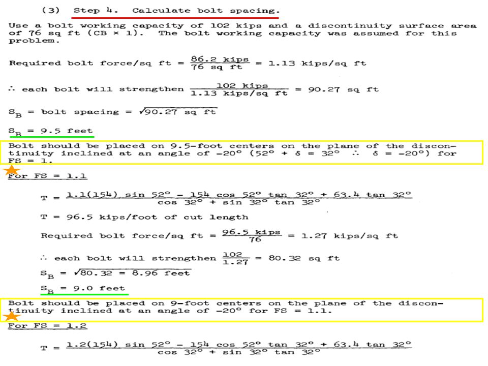
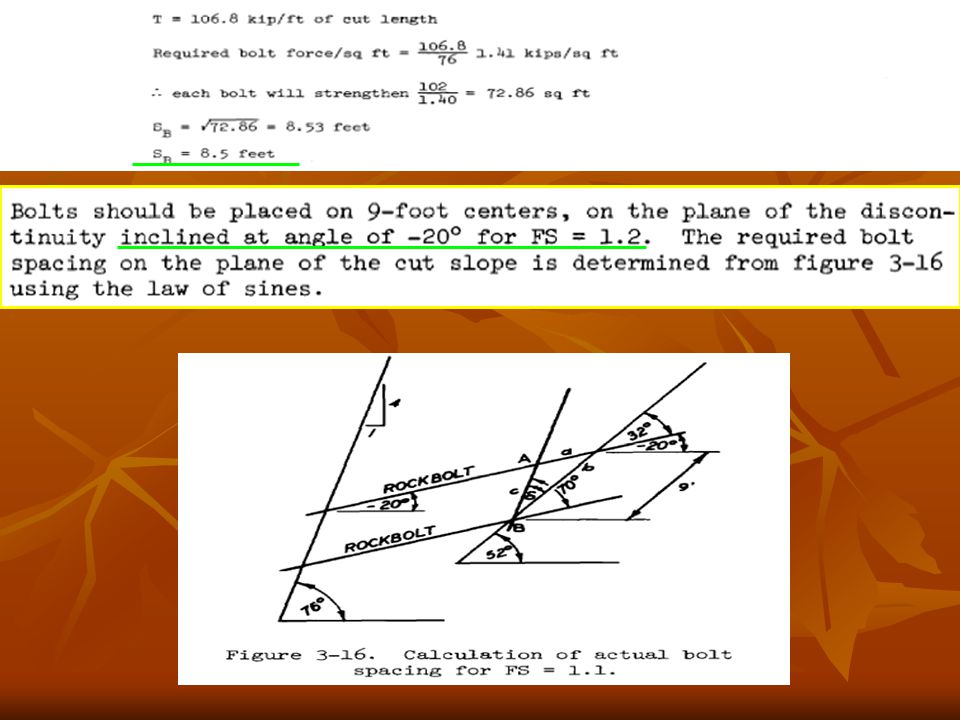
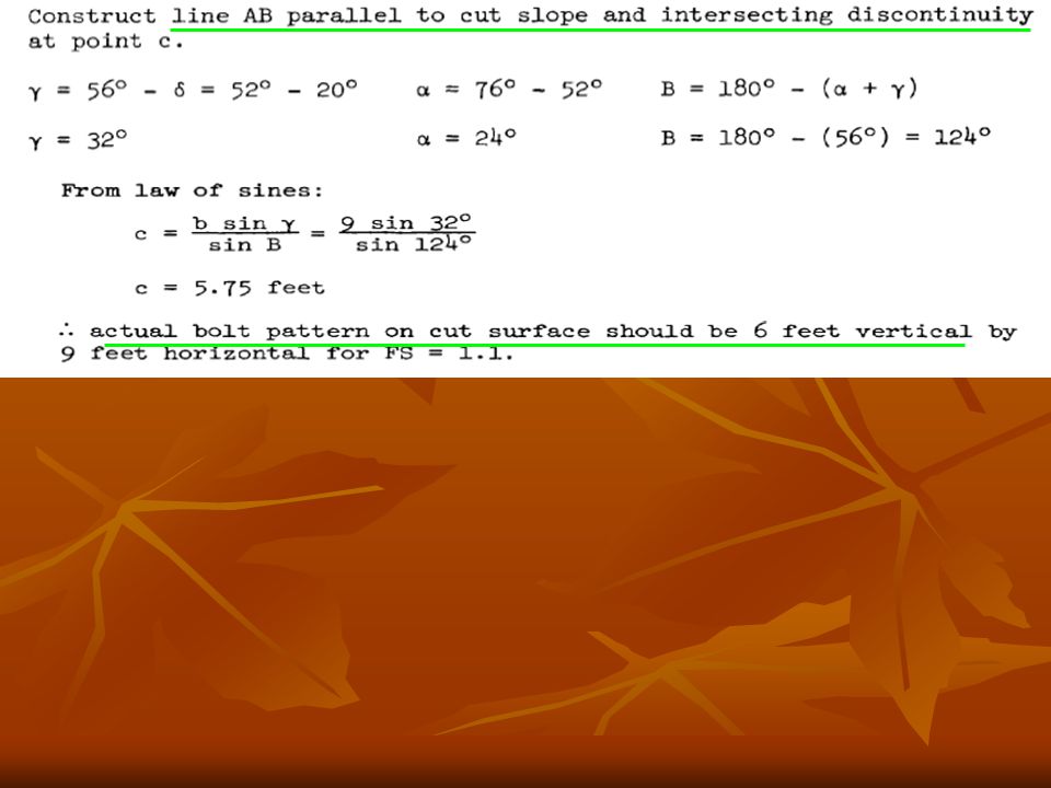
ตัวอย่างการคำนวณ

47
The bolt length can be determined graphically from figure 3-17
adding a suitable length beyond the plane of the discontinuity to satisfy anchorage requirements.


>")


>")

>")


>")


