ดาวน์โหลดงานนำเสนอ
งานนำเสนอกำลังจะดาวน์โหลด โปรดรอ

1
Chapter 3 System Buses

2
Buses อุปกรณ์ต่าง ๆ จะเชื่อมต่อกันโดยผ่านทางกลุ่มของสายสัญญาณ ที่เราเรียกว่า “บัส” อุปกรณ์ต่าง ๆ จะส่งและรับสัญญาณผ่านทางกลุ่มสายสัญญาณชุดเดียวกัน (เป็นเส้นทางเชื่อมต่อกันระหว่างอุปกรณ์)
")
3
เราสามารถแบ่งกลุ่มของบัสออกเป็น 3 กลุ่ม คือ
เราสามารถแบ่งกลุ่มของบัสออกเป็น 3 กลุ่ม คือ (Data bus) บัสข้อมูล (Address bus) บัสตำแหน่ง หรือ แอดเดรสบัส (Control bus) บัสควบคุม
 บัสข้อมูล. (Address bus) บัสตำแหน่ง หรือ แอดเดรสบัส. (Control bus) บัสควบคุม.")
4
ใช้สำหรับส่งรับข้อมูลระหว่างหน่วยต่างๆ ในระบบคอมพิวเตอร์
Data Bus ใช้สำหรับส่งรับข้อมูลระหว่างหน่วยต่างๆ ในระบบคอมพิวเตอร์ Width is a key determinant of performance 8, 16, 32, 64 bit จำนวนเส้นของสายสัญญาณใน Data Bus เรียกว่าความกว้าง (Width) ของ Data Bus และบอกถึงขนาด data word ของคอมพิวเตอร์นั้นด้วย
 ของ Data Bus และบอกถึงขนาด data word ของคอมพิวเตอร์นั้นด้วย.")
5
Address bus Identify the source or destination of data
e.g. CPU needs to read an instruction (data) from a given location in memory Bus width determines maximum memory capacity of system ใช้สำหรับแสดงตัวเลขระบุตำแหน่ง (Location) ในหน่วยความจำที่จะเข้าทำงาน ดังนั้นจำนวนเส้นของสายสัญญาณใน Address Bus (จำนวน n เส้น) จึงบอกถึงขนาดของหน่วยความจำมากที่สุดที่คอมพิวเตอร์นี้จะอ้างถึงได้คือ 2n Bytes
 from a given location in memory. Bus width determines maximum memory capacity of system. ใช้สำหรับแสดงตัวเลขระบุตำแหน่ง (Location) ในหน่วยความจำที่จะเข้าทำงาน ดังนั้นจำนวนเส้นของสายสัญญาณใน Address Bus (จำนวน n เส้น) จึงบอกถึงขนาดของหน่วยความจำมากที่สุดที่คอมพิวเตอร์นี้จะอ้างถึงได้คือ 2n Bytes.")
6
Control and timing information
Control Bus Control and timing information Memory read/write signal Interrupt request Clock signals ประกอบขึ้นด้วยสายสัญญาณที่ใช้ส่งสัญญาณไปควบคุมหน่วยต่าง ๆ ในคอมพิวเตอร์ให้ทำงานอย่างถูกต้องตามเวลาที่กำหนด (ใช้สำหรับส่งสัญญาณควบคุม

7
Control Bus ตัวอย่างของสัญญาณควบคุม
Memory Write เขียนข้อมูลที่อยู่ใน Data Bus ลงในหน่วยความจำ ที่ระบุตำแหน่งโดย Address Bus Memory Read อ่านข้อมูลที่เก็บอยู่ในหน่วยความจำ ณ ตำแหน่ง ที่ระบุโดย Address Bus เข้ามาไว้ใน Data Bus I/O Write เขียนหรือส่งข้อมูลใน Data Bus ออกไปให้แก่ I/O Port ที่ระบุโดย Address Bus I/O Read อ่านข้อมูลจาก I/O port ที่ระบุโดย Address Bus มาไว้ใน Data Bus

8
Control Bus ตัวอย่างของสัญญาณควบคุม
Transfer ACK สัญญาณสำหรับแจ้งว่าข้อมูลได้เข้ามาอยู่ใน Data Bus แล้ว Bus Request สัญญาณสำหรับแจ้งว่ามีอุปกรณ์ต้องการเข้าควบคุมบัส Interrupt Request สัญญาณแจ้งขออินเตอร์รัพท์การทำงาน CPU Interrupt ACK สัญญาณแจ้งรับทราบการอินเตอร์รัพท์ Clock สัญญาณนาฬิกา Reset เซ้ทค่าเริ่มต้นสำหรับหน่วยต่าง ๆ

9
Bus Interconnection Scheme

10
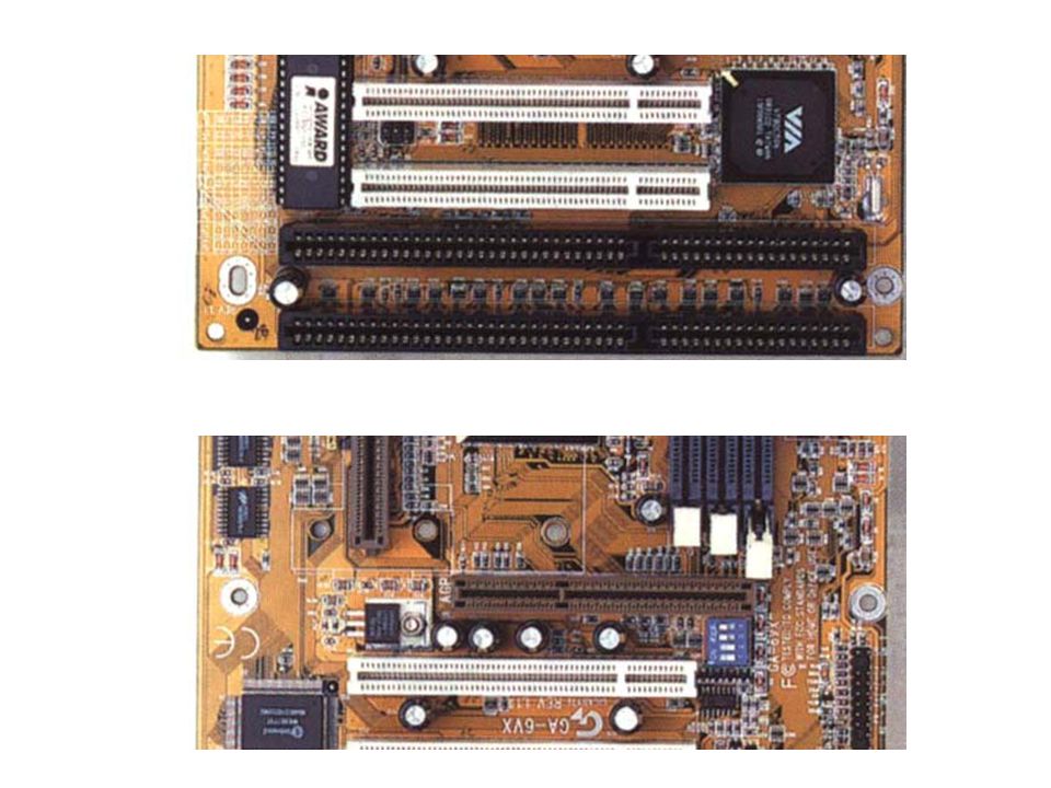
รู้จักกับ Mainboard อุปกรณ์ทางอิเลคชนิดหนึ่งที่ทำหน้าที่เป็นตัวกลางในการติดต่อสื่อสารระหว่างอุปกรณ์คอมพิวเตอร์ ซึ่งส่วนประกอบที่สำคัญบน Mainboard มีดังนี้ Socket for CPU , Chip Set , Socket for Memory, System Bus&Slot, Bios Clock, Battery, ขั้วต่ออุปกรณ์ต่างๆ , Port ต่างๆ ที่เชื่อมต่อกับอุปกรณ์ I/O

11
Socket สำหรับ CPU Pentium 4 Northwood (Socket 478) ปัจจุบันจะใช้ชนิดนี้ Pentium 4 Willamette (Socket 432) Athlon XP และ Duron ของ AMD (Socket A) ปัจจุบันจะใช้ชนิดนี้ Via C3 (Socket 370) Pentium III Tualatin/Coppermine & Celeron (Socket 370) Pentium MMX, IBM/Cyric MII (Socket 7)
 ปัจจุบันจะใช้ชนิดนี้ Via C3 (Socket 370) Pentium III Tualatin/Coppermine & Celeron (Socket 370) Pentium MMX, IBM/Cyric MII (Socket 7)")
12
Components The Control Unit and the Arithmetic and Logic Unit constitute the Central Processing Unit Arithmetic and Login Unit Control Unit Internal CPU Interconnection Registers CPU

13
Data and instructions need to get into the system and results out
Components Data and instructions need to get into the system and results out Input/output Temporary storage of code and results is needed Main memory

14
Computer Components: Top Level View

15
หน้าที่ของคอมพิวเตอร์
หน้าที่พื้นฐานของคอมพิวเตอร์คือ การประมวลผลโปรแกรมซึ่งบรรจุไว้ด้วยข้อมูล การประมวลผลคอมพิวเตอร์ประกอบด้วยขั้นตอน 2 ขั้นตอน คือ Instruction fetch จากหน่วยความจำมาทีละคำสั่ง และ Excute instruction ประมวลผลคำสั่งนั้น

16
Instruction Cycle Two steps:
Fetch คือ CPU อ่านชุดคำสั่งจาก Memory เข้ามาเก็บไว้ใน Register Execute คือ ทำกระบวนการจาก instruction ว่าโปรแกรมให้ทำอะไร HALT จบการทำงานของโปรแกรม

17
Fetch Cycle ขั้นตอนการ fetch ว่ามีการกระทำอะไรบ้าง
Program Counter (PC) holds address of next instruction to fetch Processor fetches instruction from memory location pointed to by PC Increment PC Unless told otherwise Instruction loaded into Instruction Register (IR) Processor interprets instruction and performs required actions
 holds address of next instruction to fetch. Processor fetches instruction from memory location pointed to by PC. Increment PC. Unless told otherwise. Instruction loaded into Instruction Register (IR) Processor interprets instruction and performs required actions.")
18
Fetch Cycle ขั้นตอนการ fetch ว่ามีการกระทำอะไรบ้าง
CPU Memory PC IR MBR Execute Control Signal

19
Processor-memory Processor - I/O Data processing Control
Execute Cycle โดยทั่วไป สิ่งที่ CPU มีดังนี้(คล้ายๆ กับชุดคำสั่งทำอะไรบ้างนั่นเอง) Processor-memory data transfer between CPU and main memory Processor - I/O Data transfer between CPU and I/O module Data processing Some arithmetic or logical operation on data Control Alteration of sequence of operations e.g. jump
 Processor-memory. data transfer between CPU and main memory. Processor - I/O. Data transfer between CPU and I/O module. Data processing. Some arithmetic or logical operation on data. Control. Alteration of sequence of operations. e.g. jump.")
20
Example of Program Execution
(a) instruction format ประกอบด้วย 16 บิตโดย 4 บิตแรกเป็น OpCode ที่เหลือเป็น Address ดังรูป (b) Register ที่ใช้ประกอบไปด้วย - Program Counter(PC) = Address of instruction - Instruction Register(IR) = Instruction Being Executed - Accumulator(AC) = Temporary Storage (c) Partial List of OpCodes = Load AC from Memory = Store AC to Memory = Add to AC from Memory OpCode 0-3 Address
 instruction format ประกอบด้วย 16 บิตโดย 4 บิตแรกเป็น OpCode ที่เหลือเป็น Address ดังรูป. (b) Register ที่ใช้ประกอบไปด้วย. - Program Counter(PC) = Address of instruction. - Instruction Register(IR) = Instruction Being Executed. - Accumulator(AC) = Temporary Storage. (c) Partial List of OpCodes = Load AC from Memory = Store AC to Memory = Add to AC from Memory. OpCode 0-3 Address")
22
โปรแกรมที่จะทำการ execute คือ
Memory 300 940 301 941 302 :: 0003 0002

23
Example of Program Execution

24
Instruction Cycle - State Diagram

25
Interrupts Interrupt เป็นกลไกที่จัดเตรียมไว้เพื่อเพิ่มประสิทธิภาพในการทำงานเช่น อุปกรณ์ภายนอกส่วนใหญ่ทำงานได้ช้ากว่าความเร็ว CPU สมมุตว่า CPU กำลังถ่ายโอนข้อมูลไปยังเครื่องพิมพ์หลังจากการบันทึกข้อมูล CPU ก็จะไม่มีงานทำ ต้องรอจนกว่าจะเสร็จ ชนิดของการ interrupt Program e.g. overflow, division by zero Timer Generated by internal processor timer Used in pre-emptive multi-tasking I/O from I/O controller Hardware failure e.g. memory parity error

26
Transfer of Control via Interrupts

27
Program Flow Control

28
Interrupt Cycle (เมื่อเพิ่มการ interupt จะทำอะไร)
Added to instruction cycle Processor checks for interrupt Indicated by an interrupt signal If no interrupt, fetch next instruction If interrupt pending:(ถ้า interrupt ค้างอยู่) Suspend execution of current program (พัก execution) Save context Set PC to start address of interrupt handler routine Process interrupt Restore context and continue interrupted program
 Suspend execution of current program (พัก execution) Save context. Set PC to start address of interrupt handler routine. Process interrupt. Restore context and continue interrupted program.")
29
Instruction Cycle with Interrupts

30
Program Timing Short I/O Wait

31
Program Timing Long I/O Wait

32
Instruction Cycle (with Interrupts) - State Diagram
 - State Diagram")
33
Multiple Interrupts(ในกรณีที่เกิดอินเตอร์รัพซ้อน)
Disable interrupts Processor will ignore further interrupts whilst processing one interrupt Interrupts remain pending and are checked after first interrupt has been processed Interrupts handled in sequence as they occur Define priorities Low priority interrupts can be interrupted by higher priority interrupts When higher priority interrupt has been processed, processor returns to previous interrupt

34
Multiple Interrupts - Sequential
Non Masakable interupt

35
Multiple Interrupts – Nested
Masakable interupt

36
Time Sequence of Multiple Interrupts

37
Interconnection structure ลักษณะการติดต่อสื่อสารแต่ละอุปกรณ์
All the units must be connected Different type of connection for different type of unit Memory Input/Output CPU

38
Computer Modules

39
Receives and sends data Receives addresses (of locations)
Memory Connection Receives and sends data Receives addresses (of locations) Receives control signals Read Write Timing
 Receives control signals. Read. Write. Timing.")
40
Input/Output Connection(1)
Similar to memory from computer’s viewpoint Output Receive data from computer Send data to peripheral Input Receive data from peripheral Send data to computer

41
Input/Output Connection(2)
Receive control signals from computer Send control signals to peripherals e.g. spin disk Receive addresses from computer e.g. port number to identify peripheral Send interrupt signals (control)
")
42
CPU Connection Reads instruction and data Writes out data (after processing) Sends control signals to other units Receives (& acts on) interrupts
 interrupts.")
43
Single Bus และ Multiple Bus
Single Bus เป็นระบบ bus ที่มีเส้นทางเดียวในการติดต่อกับอุปกรณ์ทั้งหมด ทำให้ระบบติดต่อกันช้า Propagation delays Long data paths mean that co-ordination of bus use can adversely affect performance If aggregate data transfer approaches bus capacity Multiple Bus (Most systems use multiple buses) เพื่อแก้ปัญหาในระบบ Single Bus
 เพื่อแก้ปัญหาในระบบ Single Bus.")
44
การใช้บัสหลายระดับ (Multiple-Bus )
อุปกรณ์บางชนิดอาจจะทำงานช้า ซึ่งถ้าให้เข้าควบคุมบัสก็จะทำให้การทำงานของบัสช้าไปด้วย ความเร็วของบัสอาจจะไม่พอที่จะให้บริการอุปกรณ์จำนวนมาก ๆ ได้ ดังนั้น เพื่อที่จะแก้ปัญหาเหล่านนี้ จึงมีการแยกเป็นระบบหลายบัส (Multiple bused) และมีการจัดลำดับความเร็วของบัสไว้ด้วย เพื่อให้บริการแก่อุปกรณ์ต่างชนิดกันดังตัวอย่างในรูป
 และมีการจัดลำดับความเร็วของบัสไว้ด้วย เพื่อให้บริการแก่อุปกรณ์ต่างชนิดกันดังตัวอย่างในรูป.")
45
Traditional (ISA) (with cache) Small Computer System Interface (SCSI)
 (with cache) Small Computer System Interface (SCSI)")
46
High Performance Bus

47
Dedicated (คือจะแยกสาย data และ address)
Bus Types มี 2 ชนิด Dedicated (คือจะแยกสาย data และ address) Separate data & address lines Multiplexed (ใช้สายร่วมกันทั้งหมด) Shared lines Address valid or data valid control line Advantage - fewer lines Disadvantages More complex control Ultimate performance
 Separate data & address lines. Multiplexed (ใช้สายร่วมกันทั้งหมด) Shared lines. Address valid or data valid control line. Advantage - fewer lines. Disadvantages. More complex control. Ultimate performance.")
48
เทคโนโลยีระบบบัส ISA Bus ส่งข้อมูลได้เร็ว 8 Mb – 12 Mb ต่อวินาที (ตั้งแต่ CPU รุ่น เป็นต้นมา ได้มีการเปลี่ยนแปลงขนาดของ เส้นทางข้อมูล จาก 8 bit ไปเป็น 16 bit ทำให้ IBM ต้องมาทำการออกแบบระบบ Bus ใหม่ เพื่อให้สามารถส่งผ่านข้อมูลทีละ 16 bit ได้ แน่นอนว่า การออกแบบใหม่นั้น ก็ต้องทำให้เข้ากันได้ย้อนหลังด้วย (Compatble) คือ ต้องสามารถใช้ งานกับ PC Bus ได้ด้วย จึงเป็นต้นแบบของ ISA Bus) MCA Bus ส่งข้อมูลได้เร็ว 20 Mb ต่อวินาที แต่ไม่เป็นที่นิยมเพราะเข้ากันไม่ได้กับ ISA บัส (ใช้กับเครื่อง IBM PS/2 ดังนั้น ในเครื่อง PS/2 นี้ก็จะไม่มี ISA และ Card ISA ก็ไม่สามารถนำมาใช้กับ PS/2 ได้ )
 คือ ต้องสามารถใช้ งานกับ PC Bus ได้ด้วย จึงเป็นต้นแบบของ ISA Bus) MCA Bus ส่งข้อมูลได้เร็ว 20 Mb ต่อวินาที แต่ไม่เป็นที่นิยมเพราะเข้ากันไม่ได้กับ ISA บัส (ใช้กับเครื่อง IBM PS/2 ดังนั้น ในเครื่อง PS/2 นี้ก็จะไม่มี ISA และ Card ISA ก็ไม่สามารถนำมาใช้กับ PS/2 ได้ )")
49
เทคโนโลยีระบบบัส EISA ใช้พื้นฐานหลักมาจาก ISA แต่ได้เพิ่มขีดความสามารถบางอย่างขึ้น ส่งข้อมูลได้เร็ว 33 Mb ต่อวินาที Local Bus เป็น Bus เฉพาะที่ เพราะใช้สัญญาณนาฬิกาเดียวกับ CPU ไม่ต้องพึ่งสัญญาณนาฬิกาพิเศษ ข้อดีของมันก็คือ ทำให้สามารถใช้สัญญาณนาฬิกาเดียวกันกับ CPU ในขณะนั้นได้ ซึ่งก็มักจะนำมาใช้กับหน่วยความจำหลัก เพื่อเพิ่มประสิทธิภาพโดยรวมของระบบ

50
เทคโนโลยีระบบบัส PCI Bus (Peripheral Computer Interconnect) ก็เป็น Local Bus อีกแบบหนึ่ง - แรกเริ่มที่เปิดตัวนั้น PCI จะเป็นบัสแบบ 32 bit ที่ทำงานด้วยความเร็ว 33 MHz ซึ่งสามารถให้อัตราเร็ว ในการส่งผ่านข้อมูลถึง 133 M/s - ต่อมา Intel Pentium ซึ่งเป็น CPU ขนาด 32 bit ทาง Intel ก็ได้ทำการกำหนดมาตราฐาน ของ PCI เสียใหม่ เป็น PCI 2.0 ซึ่ง PCI 2.0 มีความกว้างของเส้นทางข้อมูลถึง 64 bit ซึ่งหากใช้งานกับ Card 64 bit แล้ว ก็จะสามารถให้อัตราเร็วใน การส่งผ่านข้อมูลสูงสุดถึง 266 M/s - จุดเด่นของ PCI ที่เห็นได้ชัด คือสามารถทำให้ผลิต Mainboard ทีมีทั้ง Slot ISA, EISA และ PCI รวมกันได้ และ ยังสนับสนุนระบบ Plug-and-Play อีกด้วย

51
ตัวอย่างการใช้ PCI Bus กับ Single-processor system

52
ตัวอย่างการใช้ PCI Bus กับ Multiple-processor system

53
เทคโนโลยีระบบบัส AGP Bus (Accelerated Graphics Port ) เป็นสถาปัตยกรรมที่ช่วยเพิ่มประสิทธิภาพ ของหน่วยแสดงผลด้วย - สาเหตุหนึ่งที่ระบบบัสแบบ AGP ทำได้ดีกว่า PCI เพราะ เป็น Slot แบบเอกเทศ ไม่ต้องไปใช้ Bandwidth ร่วมกับใคร (เพราะเครื่อง ๆ หนึ่งมี Display Card เพียงตัวเดียวก็เพียงพอแล้ว ดังนั้น ใน Mainboard จึงมี Slot AGP เพียง Slot เดียว) ในปัจจุบัน ระบบบัสแบบ AGP ได้พัฒนามาถึง AGP 4X แล้ว ซึ่งช่วยให้เพิ่มอัตราการส่งผ่านข้อมูลได้สูงขึ้น อีกเท่าตัวจาก 2X เลยทีเดียว
 ในปัจจุบัน ระบบบัสแบบ AGP ได้พัฒนามาถึง AGP 4X แล้ว ซึ่งช่วยให้เพิ่มอัตราการส่งผ่านข้อมูลได้สูงขึ้น อีกเท่าตัวจาก 2X เลยทีเดียว.")
55
วิธีการเข้าควบคุมบัส (Method of Arbitration)
เนื่องจากในแต่ละขณะเวลา อาจจะมีอุปกรณ์หลายอันต้องการเข้าใช้บัสพร้อม ๆ กัน ดังนั้นจึงต้องมีการออกแบบการจัดการให้อุปกรณ์ต่าง ๆ เข้าควบคุมบัส ซึ่งสามารถแบ่งออกได้เป็นสองวิธีใหญ่ ๆ คือ 1. Centralized Arbiter จัดให้มีหน่วยควบคุมเพียงหน่วยเดียว ทำการจัดการในการเข้าใช้บัสของหน่วยต่าง ๆ 2. Distribute Arbiter ไม่มีหน่วยควบคุมกลาง แต่ให้แต่ละอุปกรณ์มีวงจรควบคุมเป็นของตนเอง

56
แบบฝึกหัด จากตัวอย่างการ execute program ดังนี้ (เหมือนตัวอย่าง)
(a) instruction format ประกอบด้วย 16 บิตโดย 4 บิตแรกเป็น OpCode ที่เหลือเป็น Address ดังรูป (b) Register ที่ใช้ประกอบไปด้วย - Program Counter(PC) = Address of instruction - Instruction Register(IR) = Instruction Being Executed - Accumulator(AC) = Temporary Storage (c) Partial List of OpCodes = Load AC from Memory = Store AC to Memory = Add to AC from Memory ให้เพิ่มชุดคำสั่ง 0011 = Load AC from I/O และ 0111 = Store AC to I/O และให้แสดงภาพการ Execute โดยมีลำดับการ Execute ดังนี้ Load AC from Device 5 Add Contents of memory location 940 Store AC to Device 6
 instruction format ประกอบด้วย 16 บิตโดย 4 บิตแรกเป็น OpCode ที่เหลือเป็น Address ดังรูป. (b) Register ที่ใช้ประกอบไปด้วย. - Program Counter(PC) = Address of instruction. - Instruction Register(IR) = Instruction Being Executed. - Accumulator(AC) = Temporary Storage. (c) Partial List of OpCodes = Load AC from Memory = Store AC to Memory = Add to AC from Memory. ให้เพิ่มชุดคำสั่ง 0011 = Load AC from I/O และ 0111 = Store AC to I/O และให้แสดงภาพการ Execute โดยมีลำดับการ Execute ดังนี้ Load AC from Device 5. Add Contents of memory location 940. Store AC to Device 6.")
งานนำเสนอที่คล้ายกัน


.>")
>")

 AND Extended-Data Output (EDO) DRAM>")


>")
>")


