ดาวน์โหลดงานนำเสนอ
งานนำเสนอกำลังจะดาวน์โหลด โปรดรอ

1
บทที่ 5-2 วิธีการตรวจสอบและลดข้อผิดพลาดในการสื่อสารข้อมูล
บทที่ 5-2 วิธีการตรวจสอบและลดข้อผิดพลาดในการสื่อสารข้อมูล อ. ณรงค์ฤทธิ์ มณีจิระปราการ ภาควิชาฟิสิกส์ คณะวิทยาศาสตร์ มหาวิทยาลัยนเรศวร

2
วัตถุประสงค์(Objective)
สามารถอธิบายสาเหตุที่ทำให้ข้อมูลเกิดความผิดเพี้ยนได้ อธิบายวิธีการตรวจหาความผิดพลาดของข้อมูล โดย เทคนิค Parity และ CRC อธิบายวิธีการแก้ไขความผิดพลาดของข้อมูล แบบไม่ส่ง ข้อมูลซ้ำ และส่งข้อมูลซ้ำ อธิบายวิธีการป้องกันความผิดพลาดของข้อมูลได้

3
ความผิดเพี้ยนของข้อมูล
ข้อมูลผิดเพี้ยน(error) หมายถึง ข้อมูลที่ผู้รับได้รับไม่เหมือนกับที่ผู้ส่งส่งให้ โดยปกติแล้วในระหว่างการรับ-ส่งข้อมูล หรือระหว่างการถ่ายทอดข้อมูลนั้น ข้อมูลมักจะถูกทำให้ผิดเพี้ยนไปจากเดิมเนื่องจากการรบกวนจากสิ่งต่างๆ ภายนอกระบบเครือข่ายซึ่งสามารถหลีกเลี่ยงได้แต่ไม่สามารถแก้ไขได้ และอีกส่วนหนึ่งเกิดจากปัญหาภายในระบบเองซึ่งสามารถหลีกเลี่ยงและแก้ไขได้
 หมายถึง ข้อมูลที่ผู้รับได้รับไม่เหมือนกับที่ผู้ส่งส่งให้ โดยปกติแล้วในระหว่างการรับ-ส่งข้อมูล หรือระหว่างการถ่ายทอดข้อมูลนั้น ข้อมูลมักจะถูกทำให้ผิดเพี้ยนไปจากเดิมเนื่องจากการรบกวนจากสิ่งต่างๆ ภายนอกระบบเครือข่ายซึ่งสามารถหลีกเลี่ยงได้แต่ไม่สามารถแก้ไขได้ และอีกส่วนหนึ่งเกิดจากปัญหาภายในระบบเองซึ่งสามารถหลีกเลี่ยงและแก้ไขได้")
4
สาเหตุที่ทำให้ข้อมูลผิดเพี้ยน
สาเหตุหลักที่ทำให้ข้อมูลผิดเพี้ยน สัญญาณอิมพัลส์ (Impulse Noise) สัญญาณกัสเสี้ยน(Gaussian noise or white noise) สัญญาณอ่อนกำลัง (Attenuation) ครอสทอล์ก (Crosstalk) การผิดเพี้ยนสัญญาณเนื่องจากดีเลย์ (Delay distortion) ปัญหาของสายสื่อสาร (Line Outages or line failure)
 สัญญาณกัสเสี้ยน(Gaussian noise or white noise) สัญญาณอ่อนกำลัง (Attenuation) ครอสทอล์ก (Crosstalk) การผิดเพี้ยนสัญญาณเนื่องจากดีเลย์ (Delay distortion) ปัญหาของสายสื่อสาร (Line Outages or line failure)")
5
Sources of errors include:
Impulse noise (spikes) are an important source of burst errors and can be caused by lightning, power surges, and poor connections White noise caused by thermal energy (hiss) Attenuation is the weakening of a signal over a distance Cross-talk occurs when one circuit picks up signals from another Delay distortion occurs when an amplifier does not correctly amplify its input signal Line outages in which a circuit fails
 are an important source of burst errors and can be caused by lightning, power surges, and poor connections. White noise caused by thermal energy (hiss) Attenuation is the weakening of a signal over a distance. Cross-talk occurs when one circuit picks up signals from another. Delay distortion occurs when an amplifier does not correctly amplify its input signal. Line outages in which a circuit fails.")
6
สัญญาณอิมพัลส์ – Impulse Noise
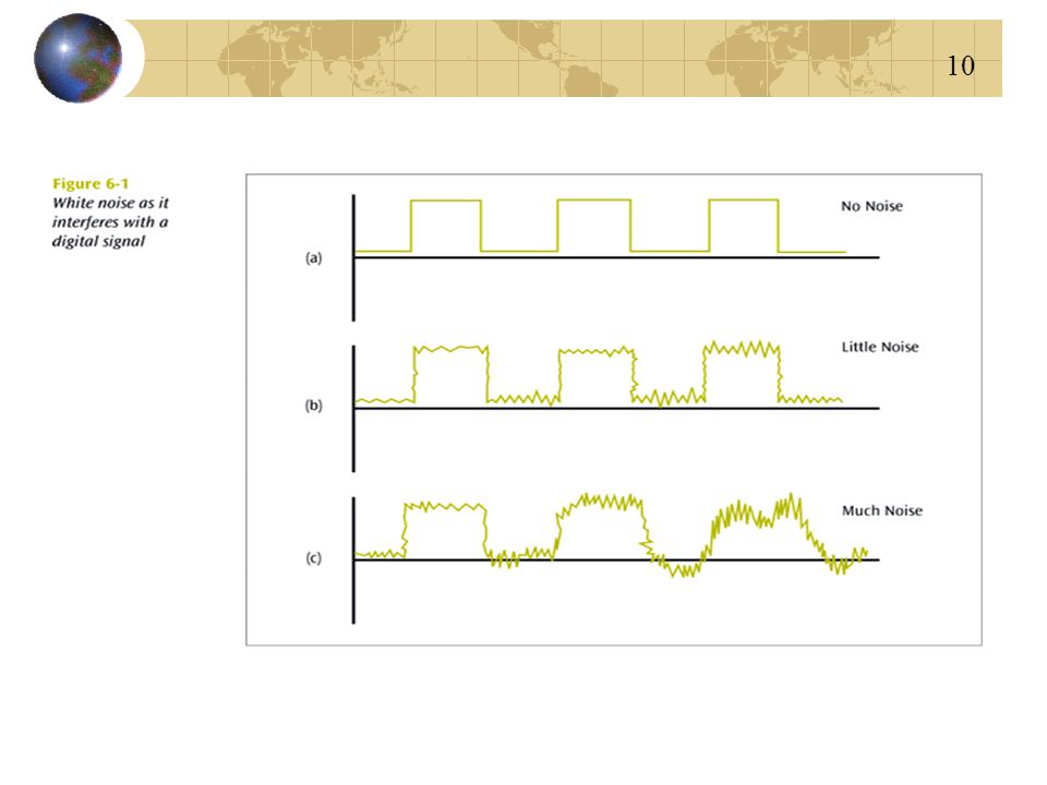
One of the most disruptive forms of noise. Random spikes of power that can destroy one or more bits of information. Difficult to remove from an analog signal because it may be hard to distinguish from the original signal. Impulse noise can damage more bits if the bits are closer together (transmitted at a faster rate).
.")
8
The bottom figure should show much more distortion, completely blowing out one or two bits of information.

9
สัญญาณกัสเสี้ยน – White Noise
Also known as thermal or Gaussian noise. Relatively constant and can be reduced. If white noise gets too strong, it can completely disrupt the signal. Solution to avoid this problem by Control media in low temperature.

11
สัญญาณอ่อนกำลัง - Attenuation
The continuous loss of a signal’s strength as it travels through a medium. All media and all signal high power of signal is more prevent from noise Solution for attenuation is regenerate signal by Amplifier (in case analog signal) or Repeater (in case digital Signal)
 or Repeater (in case digital Signal)")
12
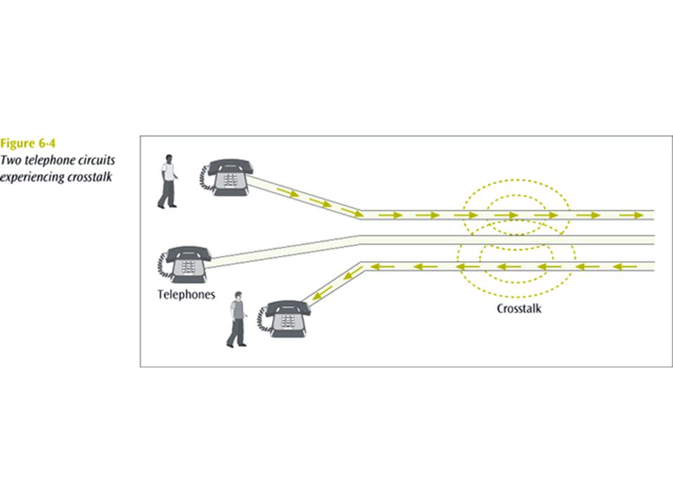
ครอสทอล์ก - Crosstalk Is unwanted coupling between two different signal paths. Cause of Noise damage of cladding too small core media too high signal For example, hearing another conversation while talking on the telephone. Relatively constant and can be reduced with proper measures.

14
การผิดเพี้ยนสัญญาณเนื่องจากดีเลย์ – Delay Distortion
Cause is Occurs because the velocity of propagation of a signal through a medium varies with the frequency of the signal. Can be reduced. Solution is use equalizer device for adjust the velocity of propagation of a signal

15
ปัญหาของสายสื่อสาร - Line Outages or Line failure
Cause is corrupt or damage of medium. Can be terminate transmission of signal. Solution is repair only by media provider

16
Sources of errors and ways to prevent or minimize them
Source of Error What causes it How to prevent it Line Outages Storms, accidents White Noise Movement of electrons Increase signal strength Impulse Noise Sudden increases in electricity (e.g., lightning) Shield or move the wires Cross-talk Multiplexer guard bands are too small or wires too close together Increase the guard bands, or move or shield the wires Echo Poor connections Fix the connections, or tune equipment Attenuation Gradual decrease in signal over distance Use repeaters or amplifiers Intermodulation Noise Signals from several circuits combine Move or shield the wires Jitter Analog signals change phase Tune equipment Harmonic Distortion Amplifier changes phase Sources of errors and ways to prevent or minimize them
 Shield or move the wires. Cross-talk. Multiplexer guard bands are too small or wires too close together. Increase the guard bands, or. move or shield the wires. Echo. Poor connections. Fix the connections, or. tune equipment. Attenuation. Gradual decrease in signal over distance. Use repeaters or amplifiers. Intermodulation Noise. Signals from several circuits combine. Move or shield the wires. Jitter. Analog signals change phase. Tune equipment. Harmonic Distortion. Amplifier changes phase. Sources of errors and ways to prevent or minimize them.")
17
วิธีการตรวจหาความผิดเพี้ยนของข้อมูล

18
Error Detection Techniques
Despite the best prevention techniques, errors may still happen. To detect an error, something extra has to be added to the data/signal. This extra is an error detection code. Let’s examine two basic techniques for detecting errors: parity checking and cyclic redundancy checksum.

19
Most error detection techniques work in the same way:
An error detection value is first calculated by the sender and transmitted along with the data. At the receiving end, the error detection value is recalculated and checked against the received value. If the two values are the same, the data has been received correctly If they differ, however, an error has occurred and the data needs to be sent again. Three common forms of error detection techniques are currently in use: parity checks, longitudinal redundancy checking, and polynomial checking.

20
Parity checking is one of the oldest and simplest error detection techniques.
In parity checking, a single bit is added to each character. For even parity, the sum of the bits (including the parity bit) remains even, for odd parity, the sum remains odd. At the receiving end, the parity bit is recalculated. If one bit has been transmitted in error the received parity bit will differ from the recalculated one. Parity checking is simple, but doesn’t catch all errors. If two (or an even number of) bits have been changed at the same time, the parity check appears to be correct even though an error has occurred.
 remains even, for odd parity, the sum remains odd. At the receiving end, the parity bit is recalculated. If one bit has been transmitted in error the received parity bit will differ from the recalculated one. Parity checking is simple, but doesn’t catch all errors. If two (or an even number of) bits have been changed at the same time, the parity check appears to be correct even though an error has occurred.")
21
Parity Checks Simple parity - If performing even parity, add a parity bit such that an even number of 1s are maintained. If performing odd parity, add a parity bit such that an odd number of 1s are maintained. For example, send using even parity For example, send using even parity

22
Assume we are using even parity with 7-bit ASCII.
The letter V in 7-bit ASCII is encoded as Because there are four 1’s (an even number), Parity is set to 0, so that the sum of all the bits remains even. This would be transmitted as: Assume we are using odd parity with 7-bit ASCII. Again, the letter V in 7-bit ASCII is encoded as Parity is set to 1, so that the sum of all the bits remains odd. This would be transmitted as:
, Parity is set to 0, so that the sum of all the bits remains even. This would be transmitted as: Assume we are using odd parity with 7-bit ASCII. Again, the letter V in 7-bit ASCII is encoded as Parity is set to 1, so that the sum of all the bits remains odd. This would be transmitted as:")
23
Parity Checks What happens if the character is sent and the first two 0s accidentally become two 1s? Thus, the following character is received: Will there be a parity error? Problem: Simple parity only detects odd numbers of bits in error.

24
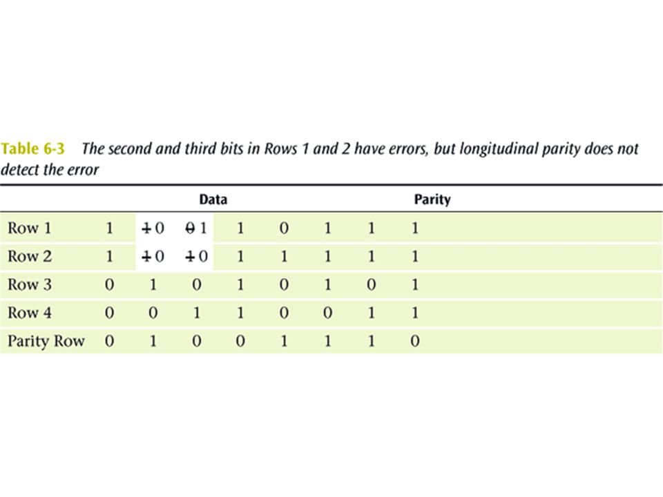
Parity Checks Longitudinal parity adds a parity bit to each character then adds a row of parity bits after a block of characters. The row of parity bits is actually a parity bit for each “column” of characters. The row parity bits plus the column parity bits add a great amount of redundancy to a block of characters.

27
Parity Checks Both simple parity and longitudinal parity do not catch all errors. Simple parity only catches odd numbers of bit errors. Longitudinal parity is better at catching errors but requires too many check bits added to a block of data. We need a better error detection method. What about cyclic redundancy checksum?

28
Error Detection: Parity Bits
Bit added to each character to make all bits add up to an even number (even parity) or odd number (odd parity) Good for detecting single-bit errors only High overhead (one extra bit per 7-bit character=12.5%)
 or odd number (odd parity) Good for detecting single-bit errors only. High overhead (one extra bit per 7-bit character=12.5%)")
29
Cyclic Redundancy Checksum
The CRC error detection method treats the packet of data to be transmitted as a large polynomial. The transmitter takes the message polynomial and using polynomial arithmetic, divides it by a given generating polynomial. The quotient is discarded but the remainder is “attached” to the end of the message.

30
Cyclic Redundancy Checksum
The message (with the remainder) is transmitted to the receiver. The receiver divides the message and remainder by the same generating polynomial. If a remainder not equal to zero results, there was an error during transmission. If a remainder of zero results, there was no error during transmission.
 is transmitted to the receiver. The receiver divides the message and remainder by the same generating polynomial. If a remainder not equal to zero results, there was an error during transmission. If a remainder of zero results, there was no error during transmission.")
32
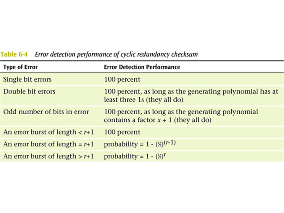
Polynomial Checking Polynomial checking, the most powerful error checking technique currently in widespread use, adds 1 or more characters to the end of the message based on a mathematical algorithm. Checksum is a 1-byte calculation made by adding the byte values of the message, dividing the total by 255 and saving the remainder (95% effective). Cyclic Redundancy Check (CRC) is also computed by calculating the remainder to a division problem. CRC- 16 (99.969% effective) and CRC-32 (99.99%) are in common use today.
. Cyclic Redundancy Check (CRC) is also computed by calculating the remainder to a division problem. CRC- 16 (99.969% effective) and CRC-32 (99.99%) are in common use today.")
33
Cyclic Redundancy Check (CRC)
Data in frame treated as a single binary number, divided by a unique prime binary, and remainder is attached to frame 17-bit divisor leaves 16-bit remainder, 33- bit divisor leaves 32-bit remainder For a CRC of length N, errors undetected are 2-N Overhead is low (1-3%)
")
34
วิธีการแก้ไขความผิดเพี้ยนของข้อมูล

35
Forward Error Correction
ARQ techniques are also called backward error correction. The alternative, forward error correction, means the receiving device can correct incoming messages itself instead of having them resent. To do this, extra corrective information needs to be sent along with the data that allows the data to be checked and corrected by the receiver. The amount of extra information needed is usually quite a lot (50-100% of the data). This technique is useful for one way transmissions or when transmission times are very long (as with communications to spacecraft).
. This technique is useful for one way transmissions or when transmission times are very long (as with communications to spacecraft).")
36
Forward Error Correction (Figure 5-26)
One forward error correction technique, called a Hamming Code, work a bit like LRC. Extra parity values are calculated so that each data bit figures into two parity bit calculations. That means that if any one bit, either parity or data, gets changed in transmission, the change in the received data can be detected and corrected (see Figure 5-26). This technique, however, only works for one bit errors.
. This technique, however, only works for one bit errors.")
37
Figure Forward Error Correction

38
Error Correction via Retransmission
When an error is detected, it is corrected by retransmission of the data along with its error detection value. The process of requesting that a data transmission be resent is called an Automatic Repeat Request or ARQ. The three main ARQ protocols are: Stop and Wait ARQ go-back-N ARQ Continuous ARQ

39
Stop-and-Wait ARQ Stop-and-Wait ARQ is a half duplex technique that works just like it sounds. The sender first sends a packet, then waits to hear from the receiver. If the packet has been received without error, an acknowledgement (ACK) is sent back by the receiver and the next packet is sent. If the receiver detects an error in the packet that was just sent, the receiver sends back a negative acknowledgement (NAK) and the sender resends the packet again.
 is sent back by the receiver and the next packet is sent. If the receiver detects an error in the packet that was just sent, the receiver sends back a negative acknowledgement (NAK) and the sender resends the packet again.")
40
Figure 4-5. Stop and Wait ARQ

41
Go-Back-N ARQ Uses sliding-window flow control
When receiver detects error, it sends negative acknowledgment (REJ) Sender must begin transmitting again from rejected frame Transmitter must keep a copy of all transmitted frames
 Sender must begin transmitting again from rejected frame. Transmitter must keep a copy of all transmitted frames.")
42
Continuous ARQ Continuous ARQ is a full duplex technique that allows the sender to continue sending packets without waiting for the receiver to acknowledge that they have been received correctly. Acknowledgements are still sent back by the receiver once they have been processed and include some kind information to identify which packet was acknowledged. If a packet is received in error, the receiver sends back a NAK for a specific packet to be resent.

43
Figure Continuous ARQ

44
Error Detection and Error Control in Action
Asynchronous transfer mode (ATM) incorporates many types of error detection and error control. ATM inserts a CRC into the data frame (the cell), which checks only the header and not the data. This CRC is also powerful enough to perform simple error correction on the header. A second layer of ATM applies a CRC to the data, with varying degrees of error control.
 incorporates many types of error detection and error control. ATM inserts a CRC into the data frame (the cell), which checks only the header and not the data. This CRC is also powerful enough to perform simple error correction on the header. A second layer of ATM applies a CRC to the data, with varying degrees of error control.")
45
การป้องกันความผิดเพี้ยนของข้อมูล

46
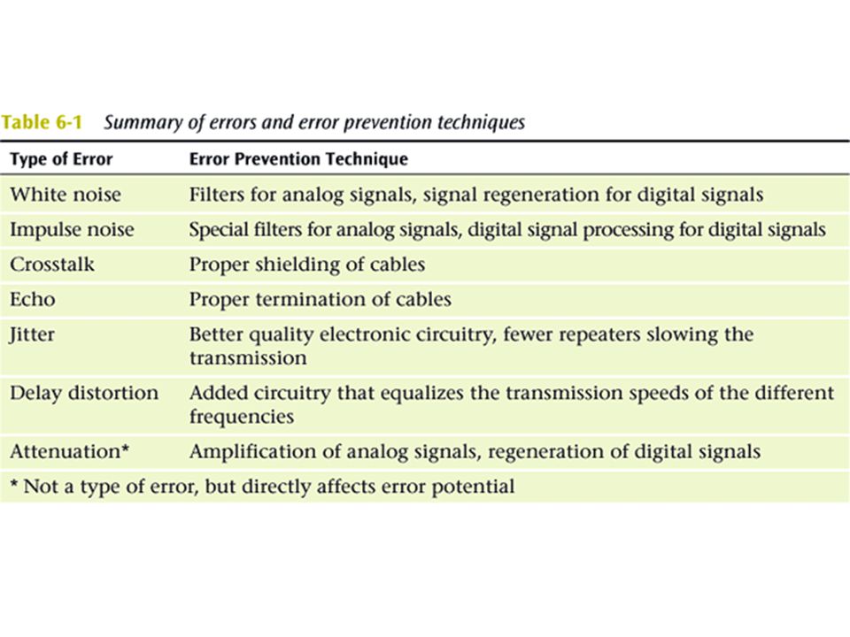
Error Prevention To prevent errors from happening, several techniques may be applied: - Proper shielding of cables to reduce interference - Telephone line conditioning or equalization - Replacing older media and equipment with new, possibly digital components - Proper use of digital repeaters and analog amplifiers - Observe the stated capacities of the media

งานนำเสนอที่คล้ายกัน


 ในช่วงยุค Internet เพิ่ง เริ่มต้น เป็นบริษัทที่ดำเนินงานทางด้าน.>")


