ดาวน์โหลดงานนำเสนอ
งานนำเสนอกำลังจะดาวน์โหลด โปรดรอ

1
for Optical Spectroscopy
ภาควิชาเคมี คณะวิทยาศาสตร์ จุฬาลงกรณ์มหาวิทยาลัย Instruments for Optical Spectroscopy ผศ.สุชาดา จูอนุวัฒนกุล

2
Instruments for Optical Spectroscopy
ส่วนประกอบพื้นฐานของเครื่องมือวิเคราะห์สำหรับ emission, absorption และ fluorescence spectroscopy เหมือนกัน ไม่ว่าจะเป็นเครื่องมือที่ใช้กับ UV, visible หรือ IR radiation จึงมักเรียกว่า optical instrument แม้ว่าจะใช้สำหรับช่วงสเปกตรัมที่ตามองไม่เห็น ส่วนประกอบพื้นฐานของ analytical instrument สำหรับ emission, absorption,และ fluorescence spectroscopy เหมือนกัน ไม่ว่าจะเป็นเครื่องมือที่ออกแบบสำหรับใช้กับ UV, visible หรือ IR radiation จึงมักเรียกว่า optical instrument แม้ว่าจะใช้สำหรับช่วง spectrum ที่ตามองไม่เห็น Spectroscopic instruments ส่วนใหญ่ ประกอบด้วย 5 ส่วน 1. stable source of radiant energy 2. wavelength selector ใช้แยก wavelength ในช่วงที่กำหนด 3. sample container 1 อัน หรือมากกว่า 4. radiation detector หรือ transducer ซึ่งเปลี่ยน radiant power ไปเป็น signal ที่สามารถวัดได้ โดยปกติจะเปลี่ยนเป็น electric signal 5. signal processor และ readout

3
Instruments for Optical Spectroscopy
เครื่องมือสำหรับสเปกโทรสโกปี (spectroscopic instruments) ส่วนใหญ่ประกอบด้วย 5 ส่วน คือ 1. แหล่งกำเนิดรังสี (radiation source) 2. ตัวเลือกความยาวคลื่น (wavelength selector) 3. ภาชนะบรรจุตัวอย่าง (sample container) 4. ตัวตรวจวัดรังสี/ตัวแปลงรังสี (radiation detector/transducer) 5. ตัวประมวลสัญญาณ (signal processor) และอุปกรณ์อ่านผล (readout) ส่วนประกอบพื้นฐานของ analytical instrument สำหรับ emission, absorption,และ fluorescence spectroscopy เหมือนกัน ไม่ว่าจะเป็นเครื่องมือที่ออกแบบสำหรับใช้กับ UV, visible หรือ IR radiation จึงมักเรียกว่า optical instrument แม้ว่าจะใช้สำหรับช่วง spectrum ที่ตามองไม่เห็น Spectroscopic instruments ส่วนใหญ่ ประกอบด้วย 5 ส่วน 1. stable source of radiant energy 2. wavelength selector ใช้แยก wavelength ในช่วงที่กำหนด 3. sample container 1 อัน หรือมากกว่า 4. radiation detector หรือ transducer ซึ่งเปลี่ยน radiant power ไปเป็น signal ที่สามารถวัดได้ โดยปกติจะเปลี่ยนเป็น electric signal 5. signal processor และ readout
 ส่วนใหญ่ประกอบด้วย 5 ส่วน คือ. 1. แหล่งกำเนิดรังสี (radiation source) 2. ตัวเลือกความยาวคลื่น (wavelength selector) 3. ภาชนะบรรจุตัวอย่าง (sample container) 4. ตัวตรวจวัดรังสี/ตัวแปลงรังสี (radiation detector/transducer) 5. ตัวประมวลสัญญาณ (signal processor) และอุปกรณ์อ่านผล (readout) ส่วนประกอบพื้นฐานของ analytical instrument สำหรับ emission, absorption,และ fluorescence spectroscopy เหมือนกัน ไม่ว่าจะเป็นเครื่องมือที่ออกแบบสำหรับใช้กับ UV, visible หรือ IR radiation จึงมักเรียกว่า optical instrument แม้ว่าจะใช้สำหรับช่วง spectrum ที่ตามองไม่เห็น. Spectroscopic instruments ส่วนใหญ่ ประกอบด้วย 5 ส่วน. 1. stable source of radiant energy. 2. wavelength selector ใช้แยก wavelength ในช่วงที่กำหนด. 3. sample container 1 อัน หรือมากกว่า. 4. radiation detector หรือ transducer ซึ่งเปลี่ยน radiant power ไปเป็น. signal ที่สามารถวัดได้ โดยปกติจะเปลี่ยนเป็น electric signal. 5. signal processor และ readout.")
4
Absorption spectrometer
Wavelength Selector Detector Source Sample Container Signal Processor and Readout Source & Sample Container Emission spectrometer Detector Wavelength Selector Signal Processor and Readout Fluorescence spectrometer Wavelength Selector (2) Source Sample Container Signal Processor and Readout Selector (1) Detector รูปที่ 23 แสดงส่วนประกอบต่าง ๆ ในเครื่องมือสำหรับ emission, absorption และ fluorescence spectroscopy Emission instruments ต่างจากเครื่องมืออีก 2 ชนิด คือ ไม่ต้องใช้ external radiation source ตัว sample จะเป็นตัวคายรังสี (emitter) เอง ส่วนประกอบ (1) source และ (3) sample container จะอยู่รวมกัน นั่นคือ arc, spark, heated surface หรือ flame เป็น sample container และทำให้ sample คาย characteristic radiation Absorption และ fluorescence instruments ต้องใช้ external source of radiant energy และเซลล์สำหรับใส่สารตัวอย่าง ในการวัด absorption ลำแสงจากแหล่งกำเนิด ผ่าน wavelength selector แล้วผ่านสารตัวอย่าง แต่ในเครื่องมือบางเครื่อง ตำแหน่งของ sample และ selector อาจสลับกัน ใน fluorescence instruments เมื่อ source ทำให้สารตัวอย่างคาย characteristic fluorescence จะวัดที่มุม 90o กับ beam จาก source รูปที่ 1 ส่วนประกอบของเครื่องมือสำหรับ optical spectroscopy
 Source. Sample Container. Signal Processor and Readout. Selector (1) Detector. รูปที่ 23 แสดงส่วนประกอบต่าง ๆ ในเครื่องมือสำหรับ emission, absorption และ fluorescence spectroscopy. Emission instruments ต่างจากเครื่องมืออีก 2 ชนิด คือ ไม่ต้องใช้ external radiation source ตัว sample จะเป็นตัวคายรังสี (emitter) เอง ส่วนประกอบ (1) source และ (3) sample container จะอยู่รวมกัน นั่นคือ arc, spark, heated surface หรือ flame เป็น sample container และทำให้ sample คาย characteristic radiation. Absorption และ fluorescence instruments ต้องใช้ external source of radiant energy และเซลล์สำหรับใส่สารตัวอย่าง ในการวัด absorption ลำแสงจากแหล่งกำเนิด ผ่าน wavelength selector แล้วผ่านสารตัวอย่าง แต่ในเครื่องมือบางเครื่อง ตำแหน่งของ sample และ selector อาจสลับกัน. ใน fluorescence instruments เมื่อ source ทำให้สารตัวอย่างคาย characteristic fluorescence จะวัดที่มุม 90o กับ beam จาก source. รูปที่ 1 ส่วนประกอบของเครื่องมือสำหรับ. optical spectroscopy.")
5
Signal Processor and Readout
Instruments for Optical Spectroscopy Absorption spectrometer Wavelength Selector Detector Source Sample Container Signal Processor and Readout ในการวัด absorption รังสีจาก source จะผ่าน wavelength selector เพื่อให้ได้รังสีที่มีความยาวคลื่นตามต้องการ เมื่อรังสีที่ได้ ผ่านตัวอย่างใน sample container จะเกิดการดูดกลืนรังสี detector จะทำหน้าที่ตรวจวัดรังสี จากนั้นประมวลสัญญาณและอ่านผลด้วย signal processor และ readout ในเครื่องมือบางเครื่อง ตำแหน่งของ wavelength selector และ sample container อาจสลับกัน ส่วนประกอบพื้นฐานของ analytical instrument สำหรับ emission, absorption,และ fluorescence spectroscopy เหมือนกัน ไม่ว่าจะเป็นเครื่องมือที่ออกแบบสำหรับใช้กับ UV, visible หรือ IR radiation จึงมักเรียกว่า optical instrument แม้ว่าจะใช้สำหรับช่วง spectrum ที่ตามองไม่เห็น Spectroscopic instruments ส่วนใหญ่ ประกอบด้วย 5 ส่วน 1. stable source of radiant energy 2. wavelength selector ใช้แยก wavelength ในช่วงที่กำหนด 3. sample container 1 อัน หรือมากกว่า 4. radiation detector หรือ transducer ซึ่งเปลี่ยน radiant power ไปเป็น signal ที่สามารถวัดได้ โดยปกติจะเปลี่ยนเป็น electric signal 5. signal processor และ readout

6
Signal Processor and Readout
Instruments for Optical Spectroscopy Fluorescence spectrometer Wavelength Selector (2) Source Sample Container Signal Processor and Readout Selector (1) Detector ในการวัด fluorescence รังสีจาก source ผ่าน wavelength selector (1) เพื่อเลือก excitation wavelength เมื่อรังสีผ่านตัวอย่าง analyte จะถูกกระตุ้นและเปล่ง fluorescence จากนั้นผ่าน wavelength selector (2) เพื่อเลือก emission wavelength แล้วตรวจวัด fluorescence ในทิศทางตั้งฉากกับรังสีจาก source ส่วนประกอบพื้นฐานของ analytical instrument สำหรับ emission, absorption,และ fluorescence spectroscopy เหมือนกัน ไม่ว่าจะเป็นเครื่องมือที่ออกแบบสำหรับใช้กับ UV, visible หรือ IR radiation จึงมักเรียกว่า optical instrument แม้ว่าจะใช้สำหรับช่วง spectrum ที่ตามองไม่เห็น Spectroscopic instruments ส่วนใหญ่ ประกอบด้วย 5 ส่วน 1. stable source of radiant energy 2. wavelength selector ใช้แยก wavelength ในช่วงที่กำหนด 3. sample container 1 อัน หรือมากกว่า 4. radiation detector หรือ transducer ซึ่งเปลี่ยน radiant power ไปเป็น signal ที่สามารถวัดได้ โดยปกติจะเปลี่ยนเป็น electric signal 5. signal processor และ readout
 Source. Sample Container. Signal Processor and Readout. Selector (1) Detector. ในการวัด fluorescence รังสีจาก source ผ่าน wavelength selector (1) เพื่อเลือก excitation wavelength เมื่อรังสีผ่านตัวอย่าง analyte จะถูกกระตุ้นและเปล่ง fluorescence จากนั้นผ่าน wavelength selector (2) เพื่อเลือก emission wavelength แล้วตรวจวัด fluorescence ในทิศทางตั้งฉากกับรังสีจาก source. ส่วนประกอบพื้นฐานของ analytical instrument สำหรับ emission, absorption,และ fluorescence spectroscopy เหมือนกัน ไม่ว่าจะเป็นเครื่องมือที่ออกแบบสำหรับใช้กับ UV, visible หรือ IR radiation จึงมักเรียกว่า optical instrument แม้ว่าจะใช้สำหรับช่วง spectrum ที่ตามองไม่เห็น. Spectroscopic instruments ส่วนใหญ่ ประกอบด้วย 5 ส่วน. 1. stable source of radiant energy. 2. wavelength selector ใช้แยก wavelength ในช่วงที่กำหนด. 3. sample container 1 อัน หรือมากกว่า. 4. radiation detector หรือ transducer ซึ่งเปลี่ยน radiant power ไปเป็น. signal ที่สามารถวัดได้ โดยปกติจะเปลี่ยนเป็น electric signal. 5. signal processor และ readout.")
7
Signal Processor and Readout
Instruments for Optical Spectroscopy Source & Sample Container Emission spectrometer Detector Wavelength Selector Signal Processor and Readout เครื่องมือสำหรับวัด emission ไม่ต้องใช้ radiation source ตัวอย่างจะถูกป้อนเข้าสู่ plasma, flame หรือ heated surface ซึ่งให้พลังงาน ทำให้ analyte ในตัวอย่างเปล่งรังสี จากนั้นตรวจวัดรังสีที่เปล่งออกมา ประมวลสัญญาณและอ่านผล ส่วนประกอบพื้นฐานของ analytical instrument สำหรับ emission, absorption,และ fluorescence spectroscopy เหมือนกัน ไม่ว่าจะเป็นเครื่องมือที่ออกแบบสำหรับใช้กับ UV, visible หรือ IR radiation จึงมักเรียกว่า optical instrument แม้ว่าจะใช้สำหรับช่วง spectrum ที่ตามองไม่เห็น Spectroscopic instruments ส่วนใหญ่ ประกอบด้วย 5 ส่วน 1. stable source of radiant energy 2. wavelength selector ใช้แยก wavelength ในช่วงที่กำหนด 3. sample container 1 อัน หรือมากกว่า 4. radiation detector หรือ transducer ซึ่งเปลี่ยน radiant power ไปเป็น signal ที่สามารถวัดได้ โดยปกติจะเปลี่ยนเป็น electric signal 5. signal processor และ readout

8
Optical Materials วัสดุที่ใช้ในการสร้าง windows, lenses, mirrors, prisms, sample containers ของ spectroscopic instruments ต้องโปร่งใส (transparent) ในช่วงสเปกตรัมที่ใช้ ในช่วง visible นิยมใช้ silicate glass ในช่วง UV (<380 nm) ต้องใช้ fused silica หรือ quartz ในช่วง IR ใช้ halide salt (KBr, NaCl, AgCl) ส่วนประกอบพื้นฐานของ analytical instrument สำหรับ emission, absorption,และ fluorescence spectroscopy เหมือนกัน ไม่ว่าจะเป็นเครื่องมือที่ออกแบบสำหรับใช้กับ UV, visible หรือ IR radiation จึงมักเรียกว่า optical instrument แม้ว่าจะใช้สำหรับช่วง spectrum ที่ตามองไม่เห็น Spectroscopic instruments ส่วนใหญ่ ประกอบด้วย 5 ส่วน 1. stable source of radiant energy 2. wavelength selector ใช้แยก wavelength ในช่วงที่กำหนด 3. sample container 1 อัน หรือมากกว่า 4. radiation detector หรือ transducer ซึ่งเปลี่ยน radiant power ไปเป็น signal ที่สามารถวัดได้ โดยปกติจะเปลี่ยนเป็น electric signal 5. signal processor และ readout
 ในช่วงสเปกตรัมที่ใช้ ในช่วง visible นิยมใช้ silicate glass. ในช่วง UV (<380 nm) ต้องใช้ fused silica หรือ quartz. ในช่วง IR ใช้ halide salt (KBr, NaCl, AgCl) ส่วนประกอบพื้นฐานของ analytical instrument สำหรับ emission, absorption,และ fluorescence spectroscopy เหมือนกัน ไม่ว่าจะเป็นเครื่องมือที่ออกแบบสำหรับใช้กับ UV, visible หรือ IR radiation จึงมักเรียกว่า optical instrument แม้ว่าจะใช้สำหรับช่วง spectrum ที่ตามองไม่เห็น. Spectroscopic instruments ส่วนใหญ่ ประกอบด้วย 5 ส่วน. 1. stable source of radiant energy. 2. wavelength selector ใช้แยก wavelength ในช่วงที่กำหนด. 3. sample container 1 อัน หรือมากกว่า. 4. radiation detector หรือ transducer ซึ่งเปลี่ยน radiant power ไปเป็น. signal ที่สามารถวัดได้ โดยปกติจะเปลี่ยนเป็น electric signal. 5. signal processor และ readout.")
9
(Spectroscopic Sources)
แหล่งกำเนิดรังสี (Spectroscopic Sources) Absorption และ fluorescence spectrometer ต้องมี external radiation source radiation source ที่ดีควร มีเสถียรภาพ (stability) สูง นั่นคือ ให้ output power คงที่ radiant power ของ source จะแปรผันแบบ exponential กับ แรงดัน (ความต่างศักย์) ของแหล่งจ่ายไฟฟ้า ดังนั้นจึงมักใช้ ตัวคุมค่าแรงดัน (voltage regulator) ให้รังสีที่มีความเข้ม (intensity) สูง สามารถตรวจวัดได้ง่าย ให้รังสีที่มี spectral range กว้าง แหล่งกำเนิดรังสี กำลังการแผ่รังสี (radiant power) ของแหล่งกำเนิดรังสี จะแปรผันแบบ exponential กับความต่างศักย์ของแหล่งจ่ายไฟฟ้า ดังนั้นจึงมักใช้ เครื่องคุมค่าความต่างศักย์ (voltage regulator)
 Absorption และ fluorescence spectrometer ต้องมี external radiation source. radiation source ที่ดีควร. มีเสถียรภาพ (stability) สูง นั่นคือ ให้ output power คงที่ radiant power ของ source จะแปรผันแบบ exponential กับ. แรงดัน (ความต่างศักย์) ของแหล่งจ่ายไฟฟ้า ดังนั้นจึงมักใช้ ตัวคุมค่าแรงดัน (voltage regulator) ให้รังสีที่มีความเข้ม (intensity) สูง สามารถตรวจวัดได้ง่าย. ให้รังสีที่มี spectral range กว้าง. แหล่งกำเนิดรังสี กำลังการแผ่รังสี (radiant power) ของแหล่งกำเนิดรังสี จะแปรผันแบบ exponential กับความต่างศักย์ของแหล่งจ่ายไฟฟ้า ดังนั้นจึงมักใช้ เครื่องคุมค่าความต่างศักย์ (voltage regulator)")
10
ช่วงความยาวคลื่น (nm)
ตารางที่ 1 Continuum Sources for Optical Spectroscopy แหล่งกำเนิดรังสี ช่วงความยาวคลื่น (nm) ชนิดของสเปกโทรสโกปี Xenon arc lamp Molecular fluorescence H2 and D2 lamp UV molecular absorption Tungsten/halogen lamp 240-2,500 UV/visible/near-IR molecular absorption Tungsten lamp 350-2,200 Visible/near-IR molecular absorption Nernst glower 400-20,000 IR molecular absorption Nichrome wire 750-20,000 Globar 1,200-40,000 ใน optical spectroscopy ใช้ทั้ง continuous source และ line sources Continuous Sources ให้ continuous radiation ในช่วงที่ต้องการ ใช้ใน molecular absorption methods ใน UV region ที่ใช้กันมากที่สุดคือ hydrogen and deuterium lamp (รูปที่ 24) ใน visible region ใช้ tungsten lamp (tungsten filament incandescent lamp) spectral output of typical filament bulb แสดงในรูปที่ 25
 ชนิดของสเปกโทรสโกปี Xenon arc lamp Molecular fluorescence. H2 and D2 lamp UV molecular absorption. Tungsten/halogen lamp ,500. UV/visible/near-IR molecular absorption. Tungsten lamp ,200. Visible/near-IR molecular absorption. Nernst glower ,000. IR molecular absorption. Nichrome wire ,000. Globar. 1,200-40,000. ใน optical spectroscopy ใช้ทั้ง continuous source และ line sources. Continuous Sources. ให้ continuous radiation ในช่วงที่ต้องการ. ใช้ใน molecular absorption methods. ใน UV region ที่ใช้กันมากที่สุดคือ hydrogen and deuterium lamp (รูปที่ 24) ใน visible region ใช้ tungsten lamp (tungsten filament incandescent lamp) spectral output of typical filament bulb แสดงในรูปที่ 25.")
11
ช่วงความยาวคลื่น (nm)
ตารางที่ 2 Line Sources for Spectroscopy แหล่งกำเนิดรังสี ช่วงความยาวคลื่น (nm) ชนิดของสเปกโทรสโกปี Hollow cathode lamp UV/vis Atomic absorption; atomic fluorescence Electrodeless discharge lamp Metal vapor lamp atomic fluorescence; Raman Laser UV/vis/IR Raman; molecular absorption; molecular fluorescence Line Sources ใช้ใน fluorescence และ atomic absorption spectroscopy นอกจากนี้ยังใช้ใน Raman spectroscopy, refractometry และ polarimetry Metal Vapor Lamps ที่ใช้กันมากมี 2 ชนิด คือ mercury and sodium vapors lamps ให้ few sharp lines ใน UV/visible regions Hollow Cathode Lamps ให้ line spectra สำหรับธาตุจำนวนมาก ใช้ใน atomic absorption spectroscopy และ atomic fluorescence spectroscopy
 ชนิดของสเปกโทรสโกปี Hollow cathode lamp. UV/vis. Atomic absorption; atomic fluorescence. Electrodeless discharge lamp. Metal vapor lamp. atomic fluorescence; Raman. Laser. UV/vis/IR. Raman; molecular absorption; molecular fluorescence. Line Sources. ใช้ใน fluorescence และ atomic absorption spectroscopy นอกจากนี้ยังใช้ใน Raman spectroscopy, refractometry และ polarimetry. Metal Vapor Lamps ที่ใช้กันมากมี 2 ชนิด คือ mercury and sodium vapors lamps ให้ few sharp lines ใน UV/visible regions. Hollow Cathode Lamps ให้ line spectra สำหรับธาตุจำนวนมาก ใช้ใน atomic absorption spectroscopy และ atomic fluorescence spectroscopy.")
12
(Spectroscopic Sources)
แหล่งกำเนิดรังสี (Spectroscopic Sources) ใน optical spectroscopy ใช้ทั้ง continuum sources และ line sources Continuum UV/Visible Sources ในช่วง UV นิยมใช้ deuterium lamp และ hydrogen lamp ในช่วง visible นิยมใช้ tungsten lamp ใน optical spectroscopy ใช้ทั้ง continuous source และ line sources Continuous Sources ให้ continuous radiation ในช่วงที่ต้องการ ใช้ใน molecular absorption methods ใน UV region ที่ใช้กันมากที่สุดคือ hydrogen and deuterium lamp (รูปที่ 24) ใน visible region ใช้ tungsten lamp (tungsten filament incandescent lamp) spectral output of typical filament bulb แสดงในรูปที่ 25
 ใน optical spectroscopy ใช้ทั้ง continuum sources และ line sources. Continuum UV/Visible Sources. ในช่วง UV นิยมใช้ deuterium lamp และ hydrogen lamp. ในช่วง visible นิยมใช้ tungsten lamp. ใน optical spectroscopy ใช้ทั้ง continuous source และ line sources. Continuous Sources. ให้ continuous radiation ในช่วงที่ต้องการ. ใช้ใน molecular absorption methods. ใน UV region ที่ใช้กันมากที่สุดคือ hydrogen and deuterium lamp (รูปที่ 24) ใน visible region ใช้ tungsten lamp (tungsten filament incandescent lamp) spectral output of typical filament bulb แสดงในรูปที่ 25.")
13
(Spectroscopic Sources)
แหล่งกำเนิดรังสี (Spectroscopic Sources) (ก) 10 -1 10 -2 10 -3 Wavelength, nm E (W cm2.nm1) (ข) ใน optical spectroscopy ใช้ทั้ง continuous source และ line sources Continuous Sources ให้ continuous radiation ในช่วงที่ต้องการ ใช้ใน molecular absorption methods ใน UV region ที่ใช้กันมากที่สุดคือ hydrogen and deuterium lamp (รูปที่ 24) ใน visible region ใช้ tungsten lamp (tungsten filament incandescent lamp) spectral output of typical filament bulb แสดงในรูปที่ 25 รูปที่ 2 (ก) deuterium lamp (ข) emission spectrum ของ deuterium lamp
 (ก) Wavelength, nm. E (W cm2.nm1) (ข) ใน optical spectroscopy ใช้ทั้ง continuous source และ line sources. Continuous Sources. ให้ continuous radiation ในช่วงที่ต้องการ. ใช้ใน molecular absorption methods. ใน UV region ที่ใช้กันมากที่สุดคือ hydrogen and deuterium lamp (รูปที่ 24) ใน visible region ใช้ tungsten lamp (tungsten filament incandescent lamp) spectral output of typical filament bulb แสดงในรูปที่ 25. รูปที่ 2 (ก) deuterium lamp. (ข) emission spectrum ของ deuterium lamp.")
14
(Spectroscopic Sources)
แหล่งกำเนิดรังสี (Spectroscopic Sources) Intensity Wavelength, nm ใน optical spectroscopy ใช้ทั้ง continuous source และ line sources Continuous Sources ให้ continuous radiation ในช่วงที่ต้องการ ใช้ใน molecular absorption methods ใน UV region ที่ใช้กันมากที่สุดคือ hydrogen and deuterium lamp (รูปที่ 24) ใน visible region ใช้ tungsten lamp (tungsten filament incandescent lamp) spectral output of typical filament bulb แสดงในรูปที่ 25 (ก) (ข) รูปที่ 3 (ก) tungsten lamp. (ข) emission spectrum ของ tungsten lamp
 Intensity. Wavelength, nm ใน optical spectroscopy ใช้ทั้ง continuous source และ line sources. Continuous Sources. ให้ continuous radiation ในช่วงที่ต้องการ. ใช้ใน molecular absorption methods. ใน UV region ที่ใช้กันมากที่สุดคือ hydrogen and deuterium lamp (รูปที่ 24) ใน visible region ใช้ tungsten lamp (tungsten filament incandescent lamp) spectral output of typical filament bulb แสดงในรูปที่ 25. (ก) (ข) รูปที่ 3 (ก) tungsten lamp. (ข) emission spectrum ของ tungsten lamp.")
15
Wavelength Selectors ทำหน้าที่แยก polychromatic radiation (รังสีหลายความยาวคลื่น) ให้เป็น monochromatic radiation (รังสีความยาวคลื่นเดียว) ในทางปฏิบัติ รังสีที่ได้จะไม่ใช่ monochromatic radiation แต่จะมีความยาวคลื่นในช่วงแคบๆ เรียกว่า band (แถบ) Polychromatic radiation Monochromatic radiation Wavelength Selector Wavelength Selectors ใช้แยก polychromatic radiation ให้เป็น monochromatic radiation Ideal ต้องการให้ output จาก wavelength selector เป็น radiation ที่มี wavelength (frequency) เดียว ในทางปฏิบัติ ไม่มี wavelength selector ที่ให้ single wavelength แต่จะให้ช่วงของ wavelength ที่ต่อเนื่อง เรียกว่า band ซึ่งเป็น Gaussian-shaped distribution of wavelengths (Figure 26 )
 Polychromatic. radiation. Monochromatic. radiation. Wavelength. Selector. Wavelength Selectors. ใช้แยก polychromatic radiation ให้เป็น monochromatic radiation. Ideal ต้องการให้ output จาก wavelength selector เป็น radiation ที่มี wavelength (frequency) เดียว. ในทางปฏิบัติ ไม่มี wavelength selector ที่ให้ single wavelength แต่จะให้ช่วงของ wavelength ที่ต่อเนื่อง เรียกว่า band ซึ่งเป็น Gaussian-shaped distribution of wavelengths (Figure 26 )")
16
Intensity wavelength Wavelength Selector polychromatic radiation
Monochromatic radiation wavelength Intensity polychromatic radiation source emission band Wavelength Selectors ใช้แยก polychromatic radiation ให้เป็น monochromatic radiation Ideal ต้องการให้ output จาก wavelength selector เป็น radiation ที่มี wavelength (frequency) เดียว ในทางปฏิบัติ ไม่มี wavelength selector ที่ให้ single wavelength แต่จะให้ช่วงของ wavelength ที่ต่อเนื่อง เรียกว่า band ซึ่งเป็น Gaussian-shaped distribution of wavelengths (Figure 26 )
 เดียว. ในทางปฏิบัติ ไม่มี wavelength selector ที่ให้ single wavelength แต่จะให้ช่วงของ wavelength ที่ต่อเนื่อง เรียกว่า band ซึ่งเป็น Gaussian-shaped distribution of wavelengths (Figure 26 )")
17
รูปที่ 4 Output of a typical wavelength selector.
100 50 ความยาวคลื่น, nm % transmittance %T ความยาวคลื่นที่ระบุ Effective bandwidth 1/2 Peak height นิยามว่า effective bandwidth หรือ bandwidth คือ ความกว้างของband ที่ half-peak height ในหน่วยความยาวคลื่น bandwidth แปรผันกลับกับคุณภาพของเครื่องมือ ถ้า bandwidth แคบ แสดงว่า เครื่องมือมีสมรรถนะสูง

18
Wavelength Selectors การแยกรังสีให้เป็นแถบแคบๆ
เพิ่ม selectivity และ sensitivity ของเครื่องมือ ลดการเบี่ยงเบนจาก Beer’s law เนื่องจาก polychromatic radiation สำหรับการวัด absorption Wavelength Selectors ใช้แยก polychromatic radiation ให้เป็น monochromatic radiation Ideal ต้องการให้ output จาก wavelength selector เป็น radiation ที่มี wavelength (frequency) เดียว ในทางปฏิบัติ ไม่มี wavelength selector ที่ให้ single wavelength แต่จะให้ช่วงของ wavelength ที่ต่อเนื่อง เรียกว่า band ซึ่งเป็น Gaussian-shaped distribution of wavelengths (Figure 26 )
 เดียว. ในทางปฏิบัติ ไม่มี wavelength selector ที่ให้ single wavelength แต่จะให้ช่วงของ wavelength ที่ต่อเนื่อง เรียกว่า band ซึ่งเป็น Gaussian-shaped distribution of wavelengths (Figure 26 )")
19
Sensitivity สภาพไว (Sensitivity) ของเครื่องมือหรือวิธี หมายถึงความสามารถของเครื่องมือหรือวิธีในการจำแนกความแตกต่างของความเข้มข้นของ analyte ที่มีค่าน้อยๆ ปัจจัยที่มีผลต่อ sensitivity คือ 1. ความชัน (slope) ของ calibration curve : ถ้า calibration curve มีความชันมาก sensitivity จะสูง 2. สภาพทำซ้ำได้ (reproducibility) หรือความเที่ยง (precision) ของเครื่องมือวัด : ถ้า reproducibility หรือ precision สูง sensitivity จะสูง Sensitivity and Detection Limit for Instruments Sensitivity of an instrument or a method measures its ability to discriminate between small differences in analyte concentration. Two factors limit sensitivity. 1. Slope of calibration curve 2. Reproducibility or precision of measuring device For two methods having equal precision, the one having the steeper calibration curve will be the more sensitive. If two methods have calibration curves with equal slopes, the one exhibiting the better precision will be the more sensitive.
 ของเครื่องมือหรือวิธี หมายถึงความสามารถของเครื่องมือหรือวิธีในการจำแนกความแตกต่างของความเข้มข้นของ analyte ที่มีค่าน้อยๆ. ปัจจัยที่มีผลต่อ sensitivity คือ. 1. ความชัน (slope) ของ calibration curve : ถ้า calibration curve มีความชันมาก sensitivity จะสูง. 2. สภาพทำซ้ำได้ (reproducibility) หรือความเที่ยง. (precision) ของเครื่องมือวัด : ถ้า reproducibility หรือ precision สูง sensitivity จะสูง. Sensitivity and Detection Limit for Instruments. Sensitivity of an instrument or a method measures its ability to discriminate between small differences in analyte concentration. Two factors limit sensitivity. 1. Slope of calibration curve. 2. Reproducibility or precision of measuring device. For two methods having equal precision, the one having the steeper calibration curve will be the more sensitive. If two methods have calibration curves with equal slopes, the one exhibiting the better precision will be the more sensitive.")
20
Detection Limit ขีดจำกัดการตรวจวัด (Detection limit or Limit of detection, LOD) คือความเข้มข้นหรือน้ำหนักต่ำสุดของ analyte ที่สามารถตรวจวัดได้ที่ระดับความเชื่อมั่นที่กำหนด Detection limit ขึ้นกับอัตราส่วนของ analytical signal กับขนาดของการแปรปรวนของ blank signal Detection limit is the minimum concentration or weight of analyte that can be detected at a known confidence level. Detection limit depends upon the ratio of the magnetude of the analytical signal to the size of the statistical fluctuations in the blank signal.
 คือความเข้มข้นหรือน้ำหนักต่ำสุดของ analyte ที่สามารถตรวจวัดได้ที่ระดับความเชื่อมั่นที่กำหนด. Detection limit ขึ้นกับอัตราส่วนของ analytical signal กับขนาดของการแปรปรวนของ blank signal. Detection limit is the minimum concentration or weight of analyte that can be detected at a known confidence level. Detection limit depends upon the ratio of the magnetude of the analytical signal to the size of the statistical fluctuations in the blank signal.")
21
Signal, Noise สัญญาณ (Signal) คือ ค่าเฉลี่ยของ output เครื่องมือวัด
เป็นสัญญาณที่ไม่ควรมีหรือมีน้อยที่สุด เกิดจากการแปรปรวนของ output ของเครื่องมือวิเคราะห์ วัดได้โดยใช้ค่าเบี่ยงเบนมาตรฐาน (standard deviation) ของสัญญาณ อัตราส่วนของสัญญาณต่อสัญญาณรบกวน (Signal-to-noise ratio, S/N) อัตราส่วนของค่าเฉลี่ยของ output / standard deviation ถ้าอัตราส่วนนี้มีค่าสูงแสดงว่าค่าที่วัดได้มีคุณภาพดี Noise Fluctuations in the output of an analytical instrument. Signal Average value of the output of an electronic device. Standard deviation of the signal is a measure of the noise. Signal - to - noise ratio (S/N) Ratio of the average value of output signal / standard deviation
 ของสัญญาณ. อัตราส่วนของสัญญาณต่อสัญญาณรบกวน. (Signal-to-noise ratio, S/N) อัตราส่วนของค่าเฉลี่ยของ output / standard deviation ถ้าอัตราส่วนนี้มีค่าสูงแสดงว่าค่าที่วัดได้มีคุณภาพดี Noise. Fluctuations in the output of an analytical instrument. Signal. Average value of the output of an electronic device. Standard deviation of the signal is a measure of the noise. Signal - to - noise ratio (S/N) Ratio of the average value of output signal / standard deviation.")
22
ช่วงความยาวคลื่น (nm)
ตารางที่ 3 Wavelength Selectors for Spectroscopy ชนิด ช่วงความยาวคลื่น (nm) หมายเหตุ ต่อเนื่อง Grating Monochromator 100 – 40,000 3000 lines/mm สำหรับ vacuum UV 50 lines/mm สำหรับ far IR Prism Monochromator 120 – 30,000 monochromator ให้ bandwidth แคบกว่า filter ไม่ต่อเนื่อง Interference Filter 200 – 14,000 Absorption Filter 380 – 750
 หมายเหตุ ต่อเนื่อง. Grating Monochromator. 100 – 40, lines/mm สำหรับ. vacuum UV. 50 lines/mm สำหรับ. far IR. Prism Monochromator. 120 – 30,000. monochromator ให้ bandwidth แคบกว่า filter. ไม่ต่อเนื่อง. Interference Filter. 200 – 14,000. Absorption Filter. 380 – 750.")
23
Radiation Filters ทำงานโดยการดูดกลืนรังสีจาก continuum source ทั้งหมด ยกเว้น band of radiation ที่ต้องการในช่วง visible Filters ที่ใช้ในสเปกโทรสโกปีมี 2 ชนิดคือ 1. Interference filters 2. Absorption filters Absorption Filter ใช้กันอย่างกว้างขวางสำหรับ band selection ใน visible region filter ชนิดนี้ทำงานโดยการดูดกลืนรังสีทั้งหมด ยกเว้นช่วงความยาวคลื่นจำกัดช่วงหนึ่ง most common type 1. colored glass of tinted glass - pigment dissolved or dispersed in glass 2. dye suspended in gelatin and sandwiched between glass plate มี thermal stability ต่ำ 3. liquid filter - colored solution in container absorption filters มี effective bandwidths ในช่วง nm filter ที่ให้ bandwidths แคบที่สุด จะดูดกลืนรังสีที่ต้องการเป็นปริมาณมากด้วย จึงอาจมี transmittance ฃ 1% ที่ band peaks Cut-off filters ดูดกลืนรังสีที่มี wavelength สูงกว่าค่าหนึ่ง (high cutoff) หรือ ต่ำกว่าค่าหนึ่ง (low cutoff) ในการวัด absorption มักใช้ interfernce filters เนื่องจากสามารถส่งผ่านรังสีที่ความยาวคลื่นที่ระบุได้มากกว่า absorption filters
 หรือ. ต่ำกว่าค่าหนึ่ง (low cutoff) ในการวัด absorption มักใช้ interfernce filters เนื่องจากสามารถส่งผ่านรังสีที่ความยาวคลื่นที่ระบุได้มากกว่า absorption filters.")
24
Absorption Filters เป็นแผ่นแก้วสี ทำงานโดยการดูดกลืน (absorption) รังสี ใช้สำหรับเลือก band ในช่วง visible effective bandwidths 30–250 nm ถ้า effective bandwidth ยิ่งแคบ %transmittance จะมีค่ายิ่งน้อย Absorption Filter ใช้กันอย่างกว้างขวางสำหรับ band selection ใน visible region filter ชนิดนี้ทำงานโดยการดูดกลืนรังสีทั้งหมด ยกเว้นช่วงความยาวคลื่นจำกัดช่วงหนึ่ง most common type 1. colored glass of tinted glass - pigment dissolved or dispersed in glass 2. dye suspended in gelatin and sandwiched between glass plate มี thermal stability ต่ำ 3. liquid filter - colored solution in container absorption filters มี effective bandwidths ในช่วง nm filter ที่ให้ bandwidths แคบที่สุด จะดูดกลืนรังสีที่ต้องการเป็นปริมาณมากด้วย จึงอาจมี transmittance ฃ 1% ที่ band peaks Cut-off filters ดูดกลืนรังสีที่มี wavelength สูงกว่าค่าหนึ่ง (high cutoff) หรือ ต่ำกว่าค่าหนึ่ง (low cutoff)
 หรือ. ต่ำกว่าค่าหนึ่ง (low cutoff)")
25
Absorption Filter Wavelength Selectors ใช้แยก polychromatic radiation ให้เป็น monochromatic radiation Ideal ต้องการให้ output จาก wavelength selector เป็น radiation ที่มี wavelength (frequency) เดียว ในทางปฏิบัติ ไม่มี wavelength selector ที่ให้ single wavelength แต่จะให้ช่วงของ wavelength ที่ต่อเนื่อง เรียกว่า band ซึ่งเป็น Gaussian-shaped distribution of wavelengths (Figure 26 ) รูปที่ 5 absorption filter สีม่วงจะดูดกลืนแสงสีเขียว ในขณะที่แสงสีม่วง (แดงและน้ำเงิน) ผ่านได้
 เดียว. ในทางปฏิบัติ ไม่มี wavelength selector ที่ให้ single wavelength แต่จะให้ช่วงของ wavelength ที่ต่อเนื่อง เรียกว่า band ซึ่งเป็น Gaussian-shaped distribution of wavelengths (Figure 26 ) รูปที่ 5 absorption filter สีม่วงจะดูดกลืนแสงสีเขียว ในขณะที่แสงสีม่วง (แดงและน้ำเงิน) ผ่านได้")
26
Cut–off Filter Cut-off filter เป็น absorption filter ที่ดูดกลืนรังสีที่มีความยาวคลื่นสูงกว่าค่าหนึ่ง (Long pass filter) หรือต่ำกว่าค่าหนึ่ง (Short pass filter) Wavelength (nm) % Transmittance (%T) Short pass filter Long pass filter
 หรือต่ำกว่าค่าหนึ่ง (Short pass filter) Wavelength (nm) % Transmittance (%T) Short pass filter. Long pass filter.")
27
Absorption Filter รูปที่ 6 Comparison of various types of filters
for visible region Absorption Filter ใช้กันอย่างกว้างขวางสำหรับ band selection ใน visible region filter ชนิดนี้ทำงานโดยการดูดกลืนรังสีทั้งหมด ยกเว้นช่วงความยาวคลื่นจำกัดช่วงหนึ่ง most common type 1. colored glass of tinted glass - pigment dissolved or dispersed in glass 2. dye suspended in gelatin and sandwiched between glass plate มี thermal stability ต่ำ 3. liquid filter - colored solution in container absorption filters มี effective bandwidths ในช่วง nm filter ที่ให้ bandwidths แคบที่สุด จะดูดกลืนรังสีที่ต้องการเป็นปริมาณมากด้วย จึงอาจมี transmittance ฃ 1% ที่ band peaks Cut-off filters ดูดกลืนรังสีที่มี wavelength สูงกว่าค่าหนึ่ง (high cutoff) หรือ ต่ำกว่าค่าหนึ่ง (low cutoff)
 หรือ. ต่ำกว่าค่าหนึ่ง (low cutoff)")
28
Absorption Filter Filter ใช้ได้ง่าย ราคาถูก และทนทาน
Filter อันหนึ่งใช้แยก band ที่มีความยาวคลื่นเดียว ถ้าต้องการเลือกความยาวคลื่นอื่นจะต้องเปลี่ยน filter ดังนั้นเครื่องมือที่ใช้ filter มักใช้สำหรับวัดที่ความยาวคลื่นคงที่หรือเปลี่ยนความยาวคลื่นไม่บ่อยนัก Absorption Filter ใช้กันอย่างกว้างขวางสำหรับ band selection ใน visible region filter ชนิดนี้ทำงานโดยการดูดกลืนรังสีทั้งหมด ยกเว้นช่วงความยาวคลื่นจำกัดช่วงหนึ่ง most common type 1. colored glass of tinted glass - pigment dissolved or dispersed in glass 2. dye suspended in gelatin and sandwiched between glass plate มี thermal stability ต่ำ 3. liquid filter - colored solution in container absorption filters มี effective bandwidths ในช่วง nm filter ที่ให้ bandwidths แคบที่สุด จะดูดกลืนรังสีที่ต้องการเป็นปริมาณมากด้วย จึงอาจมี transmittance ฃ 1% ที่ band peaks Cut-off filters ดูดกลืนรังสีที่มี wavelength สูงกว่าค่าหนึ่ง (high cutoff) หรือ ต่ำกว่าค่าหนึ่ง (low cutoff)
 หรือ. ต่ำกว่าค่าหนึ่ง (low cutoff)")
29
Interference Filters ใช้ในช่วง UV, visible และ IR (จนถึงความยาวคลื่น 14 m) ทำงานโดยอาศัยการแทรกสอดของแสง (optical interference) effective bandwidths ค่อนข้างแคบ โดยทั่วไปคือ 5–20 nm Interference Filter อาศัย การแทรกสอดของแสง (optical interference) เพื่อให้ได้ narrow bands of radiations ประกอบด้วย transparent dielectrics* layer ที่บางมาก (ส่วนใหญ่ใช้ CaF2, MgF2) อยู่ระหว่าง 2 semitransparent metallic films ที่บางพอที่จะทำให้รังสีครึ่งหนึ่งผ่านไปได้ อีกครึ่งหนึ่งถูกสะท้อนกลับด้านนอกประกบด้วย 2 glass plates หรือ transparent materials อื่น เพื่อ protect จากบรรยากาศ ความหนาของ dielectric layer จะเป็นตัวกำหนด wavelength ของ transmitted radiation จึงต้องควบคุมอย่างระมัดระวัง Dielectrics คือ ชนิดของสารที่เป็น nonconductors เพราะไม่มี free e- หรือมีน้อยมาก โดยทั่วไป dielectric จะ optically transparent ซึ่งตรงข้ามกับ electrically conducting solids ซึ่งจะดูดกลืน (absorb) หรือสะท้อน (reflect) ได้ดี
 เพื่อให้ได้ narrow bands of radiations ประกอบด้วย transparent dielectrics* layer ที่บางมาก (ส่วนใหญ่ใช้ CaF2, MgF2) อยู่ระหว่าง 2 semitransparent metallic films ที่บางพอที่จะทำให้รังสีครึ่งหนึ่งผ่านไปได้ อีกครึ่งหนึ่งถูกสะท้อนกลับด้านนอกประกบด้วย 2 glass plates หรือ transparent materials อื่น เพื่อ protect จากบรรยากาศ ความหนาของ dielectric layer จะเป็นตัวกำหนด wavelength ของ transmitted radiation จึงต้องควบคุมอย่างระมัดระวัง. Dielectrics คือ ชนิดของสารที่เป็น nonconductors เพราะไม่มี free e- หรือมีน้อยมาก โดยทั่วไป dielectric จะ optically transparent ซึ่งตรงข้ามกับ electrically conducting solids ซึ่งจะดูดกลืน (absorb) หรือสะท้อน (reflect) ได้ดี")
30
Interference Filters White radiation Narrow band of radiation
Transparent dielectric layer of low refractive index (CaF2, MgF2 ) White radiation Narrow band of radiation Interference Filter อาศัย การแทรกสอดของแสง (optical interference) เพื่อให้ได้ narrow bands of radiations ประกอบด้วย transparent dielectrics* layer ที่บางมาก (ส่วนใหญ่ใช้ CaF2, MgF2) อยู่ระหว่าง 2 semitransparent metallic films ที่บางพอที่จะทำให้รังสีครึ่งหนึ่งผ่านไปได้ อีกครึ่งหนึ่งถูกสะท้อนกลับด้านนอกประกบด้วย 2 glass plates หรือ transparent materials อื่น เพื่อ protect จากบรรยากาศ ความหนาของ dielectric layer จะเป็นตัวกำหนด wavelength ของ transmitted radiation จึงต้องควบคุมอย่างระมัดระวัง Dielectrics คือ ชนิดของสารที่เป็น nonconductors เพราะไม่มี free e- หรือมีน้อยมาก โดยทั่วไป dielectric จะ optically transparent ซึ่งตรงข้ามกับ electrically conducting solids ซึ่งจะดูดกลืน (absorb) หรือสะท้อน (reflect) ได้ดี Glass plate Semitransparent metal film รูปที่ 7 Schematic cross section of an interference filter.
 White radiation. Narrow band of radiation. Interference Filter. อาศัย การแทรกสอดของแสง (optical interference) เพื่อให้ได้ narrow bands of radiations ประกอบด้วย transparent dielectrics* layer ที่บางมาก (ส่วนใหญ่ใช้ CaF2, MgF2) อยู่ระหว่าง 2 semitransparent metallic films ที่บางพอที่จะทำให้รังสีครึ่งหนึ่งผ่านไปได้ อีกครึ่งหนึ่งถูกสะท้อนกลับด้านนอกประกบด้วย 2 glass plates หรือ transparent materials อื่น เพื่อ protect จากบรรยากาศ ความหนาของ dielectric layer จะเป็นตัวกำหนด wavelength ของ transmitted radiation จึงต้องควบคุมอย่างระมัดระวัง. Dielectrics คือ ชนิดของสารที่เป็น nonconductors เพราะไม่มี free e- หรือมีน้อยมาก โดยทั่วไป dielectric จะ optically transparent ซึ่งตรงข้ามกับ electrically conducting solids ซึ่งจะดูดกลืน (absorb) หรือสะท้อน (reflect) ได้ดี Glass plate. Semitransparent metal film. รูปที่ 7 Schematic cross section of an interference filter.")
31
Interference Filters Interfernece filter ประกอบด้วยวัสดุไดอิเล็กตริก (dielectric) ที่บางมาก (ส่วนใหญ่ใช้ CaF2, MgF2) ทั้งสองด้านเคลือบด้วยฟิล์มของโลหะที่บางพอที่รังสีที่ตกกระทบครึ่งหนึ่งจะผ่านไปได้และอีกครึ่งหนึ่งถูกสะท้อนกลับ ด้านนอกประกบด้วยแผ่นแก้วหรือวัสดุโปร่งแสงอื่นๆ 2 แผ่นเพื่อป้องกันด้านในจากบรรยากาศ ความหนาของ dielectric layer จะเป็นตัวกำหนดความยาวคลื่นของ transmitted radiation จึงต้องควบคุมอย่างระมัดระวัง Interference Filter อาศัย การแทรกสอดของแสง (optical interference) เพื่อให้ได้ narrow bands of radiations ประกอบด้วย transparent dielectrics* layer ที่บางมาก (ส่วนใหญ่ใช้ CaF2, MgF2) อยู่ระหว่าง 2 semitransparent metallic films ที่บางพอที่จะทำให้รังสีครึ่งหนึ่งผ่านไปได้ อีกครึ่งหนึ่งถูกสะท้อนกลับด้านนอกประกบด้วย 2 glass plates หรือ transparent materials อื่น เพื่อ protect จากบรรยากาศ ความหนาของ dielectric layer จะเป็นตัวกำหนด wavelength ของ transmitted radiation จึงต้องควบคุมอย่างระมัดระวัง Dielectrics คือ ชนิดของสารที่เป็น nonconductors เพราะไม่มี free e- หรือมีน้อยมาก โดยทั่วไป dielectric จะ optically transparent ซึ่งตรงข้ามกับ electrically conducting solids ซึ่งจะดูดกลืน (absorb) หรือสะท้อน (reflect) ได้ดี
 ที่บางมาก (ส่วนใหญ่ใช้ CaF2, MgF2) ทั้งสองด้านเคลือบด้วยฟิล์มของโลหะที่บางพอที่รังสีที่ตกกระทบครึ่งหนึ่งจะผ่านไปได้และอีกครึ่งหนึ่งถูกสะท้อนกลับ ด้านนอกประกบด้วยแผ่นแก้วหรือวัสดุโปร่งแสงอื่นๆ 2 แผ่นเพื่อป้องกันด้านในจากบรรยากาศ. ความหนาของ dielectric layer จะเป็นตัวกำหนดความยาวคลื่นของ transmitted radiation จึงต้องควบคุมอย่างระมัดระวัง. Interference Filter. อาศัย การแทรกสอดของแสง (optical interference) เพื่อให้ได้ narrow bands of radiations ประกอบด้วย transparent dielectrics* layer ที่บางมาก (ส่วนใหญ่ใช้ CaF2, MgF2) อยู่ระหว่าง 2 semitransparent metallic films ที่บางพอที่จะทำให้รังสีครึ่งหนึ่งผ่านไปได้ อีกครึ่งหนึ่งถูกสะท้อนกลับด้านนอกประกบด้วย 2 glass plates หรือ transparent materials อื่น เพื่อ protect จากบรรยากาศ ความหนาของ dielectric layer จะเป็นตัวกำหนด wavelength ของ transmitted radiation จึงต้องควบคุมอย่างระมัดระวัง. Dielectrics คือ ชนิดของสารที่เป็น nonconductors เพราะไม่มี free e- หรือมีน้อยมาก โดยทั่วไป dielectric จะ optically transparent ซึ่งตรงข้ามกับ electrically conducting solids ซึ่งจะดูดกลืน (absorb) หรือสะท้อน (reflect) ได้ดี")
32
Interference Filters Dielectric คือ สารที่เป็นฉนวนไฟฟ้า (nonconductors) เพราะไม่มีอิเล็กตรอนอิสระหรือมีน้อยมาก โดยทั่วไป dielectric จะโปร่งใส (optically transparent) ซึ่งตรงข้ามกับของแข็งที่นำไฟฟ้าซึ่งจะดูดกลืน (absorb) หรือสะท้อน (reflect) แสงได้ดี Interference Filter อาศัย การแทรกสอดของแสง (optical interference) เพื่อให้ได้ narrow bands of radiations ประกอบด้วย transparent dielectrics* layer ที่บางมาก (ส่วนใหญ่ใช้ CaF2, MgF2) อยู่ระหว่าง 2 semitransparent metallic films ที่บางพอที่จะทำให้รังสีครึ่งหนึ่งผ่านไปได้ อีกครึ่งหนึ่งถูกสะท้อนกลับด้านนอกประกบด้วย 2 glass plates หรือ transparent materials อื่น เพื่อ protect จากบรรยากาศ ความหนาของ dielectric layer จะเป็นตัวกำหนด wavelength ของ transmitted radiation จึงต้องควบคุมอย่างระมัดระวัง Dielectrics คือ ชนิดของสารที่เป็น nonconductors เพราะไม่มี free e- หรือมีน้อยมาก โดยทั่วไป dielectric จะ optically transparent ซึ่งตรงข้ามกับ electrically conducting solids ซึ่งจะดูดกลืน (absorb) หรือสะท้อน (reflect) ได้ดี
 เพราะไม่มีอิเล็กตรอนอิสระหรือมีน้อยมาก โดยทั่วไป dielectric จะโปร่งใส (optically transparent) ซึ่งตรงข้ามกับของแข็งที่นำไฟฟ้าซึ่งจะดูดกลืน (absorb) หรือสะท้อน (reflect) แสงได้ดี Interference Filter. อาศัย การแทรกสอดของแสง (optical interference) เพื่อให้ได้ narrow bands of radiations ประกอบด้วย transparent dielectrics* layer ที่บางมาก (ส่วนใหญ่ใช้ CaF2, MgF2) อยู่ระหว่าง 2 semitransparent metallic films ที่บางพอที่จะทำให้รังสีครึ่งหนึ่งผ่านไปได้ อีกครึ่งหนึ่งถูกสะท้อนกลับด้านนอกประกบด้วย 2 glass plates หรือ transparent materials อื่น เพื่อ protect จากบรรยากาศ ความหนาของ dielectric layer จะเป็นตัวกำหนด wavelength ของ transmitted radiation จึงต้องควบคุมอย่างระมัดระวัง. Dielectrics คือ ชนิดของสารที่เป็น nonconductors เพราะไม่มี free e- หรือมีน้อยมาก โดยทั่วไป dielectric จะ optically transparent ซึ่งตรงข้ามกับ electrically conducting solids ซึ่งจะดูดกลืน (absorb) หรือสะท้อน (reflect) ได้ดี")
33
Interference Filter รูปที่ 8
Transmitted radiation Reflected radiation 4 3 2 1 White radiation t A B 3 2 1 Figure 29 Schematic to show the conditions for constructive interference. เมื่อ perpendicular beam of collimated radiation ตกกระทบ interference filter โดยทำมุม q กับเส้นตั้งฉากที่จุด 1 ของ first metallic layer radiation บางส่วนจะถูกสะท้อนไปยังจุด 2 และบางส่วนจะผ่านไปยัง second metallic layer ส่วนที่ผ่านไปนี้ เมื่อชน second metallic layer ที่จุด 1/ จะถูกแยกเป็น 2 ส่วนเช่นกัน ถ้าส่วนที่สะท้อนจาก second interaction มี wavelength ที่พอเหมาะ บางส่วนจะถูกสะท้อนจากด้านในของ first layer และร่วมเฟสกัน (in phase) กับ incoming light ซึ่งมี wavelength เท่ากัน ทำให้ wavelength นี้เกิด การแทรกสอดเสริม (constructive interference) ในขณะที่ wavelength อื่นซึ่งต่างเฟสกัน (out of phase) เกิด การแทรกสอดทำลาย (destructive interference) Interference filter สร้างให้ wavelengths ส่วนใหญ่ที่ตกกระทบ filter เกิด destructive interference และ small bands of wavelengths เกิด constructive interference ผ่านไปได้ รูปที่ 8 Schematic to show the conditions for constructive interference.
 กับ incoming light ซึ่งมี wavelength เท่ากัน ทำให้ wavelength นี้เกิด การแทรกสอดเสริม (constructive interference) ในขณะที่ wavelength อื่นซึ่งต่างเฟสกัน (out of phase) เกิด การแทรกสอดทำลาย (destructive interference) Interference filter สร้างให้ wavelengths ส่วนใหญ่ที่ตกกระทบ filter เกิด destructive interference และ small bands of wavelengths เกิด constructive interference ผ่านไปได้ รูปที่ 8. Schematic to show the conditions for constructive interference.")
34
Interference Filter เมื่อลำแสงขนานตกกระทบ interference filter โดยทำมุม กับเส้นตั้งฉากที่จุด 1 ของชั้นโลหะชั้นแรก รังสีบางส่วนจะสะท้อนกลับ และบางส่วนจะผ่านไปยังชั้นโลหะชั้นที่ 2 ส่วนที่ผ่านไปนี้ เมื่อชนโลหะชั้นที่ 2 ที่จุด 1 จะแยกเป็น 2 ส่วนเช่นเดียวกัน รังสีที่สะท้อนกลับจากชั้นโลหะชั้นที่ 2 บางความยาวคลื่นจะสะท้อนที่ด้านในของชั้นโลหะชั้นที่ 1 และร่วมเฟสกับรังสีที่เข้ามาใหม่ซึ่งมีความยาวคลื่นเท่ากัน ทำให้เกิดการแทรกสอดเสริม (constructive interference) และผ่าน filter ไปได้ ในขณะที่ความยาวคลื่นอื่นซึ่งต่างเฟสกัน เกิดการแทรกสอดทำลาย (destructive interference) Figure 29 Schematic to show the conditions for constructive interference. เมื่อ perpendicular beam of collimated radiation ตกกระทบ interference filter โดยทำมุม q กับเส้นตั้งฉากที่จุด 1 ของ first metallic layer radiation บางส่วนจะถูกสะท้อนไปยังจุด 2 และบางส่วนจะผ่านไปยัง second metallic layer ส่วนที่ผ่านไปนี้ เมื่อชน second metallic layer ที่จุด 1/ จะถูกแยกเป็น 2 ส่วนเช่นกัน ถ้าส่วนที่สะท้อนจาก second interaction มี wavelength ที่พอเหมาะ บางส่วนจะถูกสะท้อนจากด้านในของ first layer และร่วมเฟสกัน (in phase) กับ incoming light ซึ่งมี wavelength เท่ากัน ทำให้ wavelength นี้เกิด การแทรกสอดเสริม (constructive interference) ในขณะที่ wavelength อื่นซึ่งต่างเฟสกัน (out of phase) เกิด การแทรกสอดทำลาย (destructive interference) Interference filter สร้างให้ wavelengths ส่วนใหญ่ที่ตกกระทบ filter เกิด destructive interference และ small bands of wavelengths เกิด constructive interference ผ่านไปได้
 และผ่าน filter ไปได้ ในขณะที่ความยาวคลื่นอื่นซึ่งต่างเฟสกัน เกิดการแทรกสอดทำลาย (destructive interference) Figure 29 Schematic to show the conditions for constructive interference. เมื่อ perpendicular beam of collimated radiation ตกกระทบ interference filter โดยทำมุม q กับเส้นตั้งฉากที่จุด 1 ของ first metallic layer radiation บางส่วนจะถูกสะท้อนไปยังจุด 2 และบางส่วนจะผ่านไปยัง second metallic layer ส่วนที่ผ่านไปนี้ เมื่อชน second metallic layer ที่จุด 1/ จะถูกแยกเป็น 2 ส่วนเช่นกัน ถ้าส่วนที่สะท้อนจาก second interaction มี wavelength ที่พอเหมาะ บางส่วนจะถูกสะท้อนจากด้านในของ first layer และร่วมเฟสกัน (in phase) กับ incoming light ซึ่งมี wavelength เท่ากัน ทำให้ wavelength นี้เกิด การแทรกสอดเสริม (constructive interference) ในขณะที่ wavelength อื่นซึ่งต่างเฟสกัน (out of phase) เกิด การแทรกสอดทำลาย (destructive interference) Interference filter สร้างให้ wavelengths ส่วนใหญ่ที่ตกกระทบ filter เกิด destructive interference และ small bands of wavelengths เกิด constructive interference ผ่านไปได้")
35
Interference Filter max =
= ดัชนีหักเห (refractive index) ของไดอิเล็กตริก n = เลขจำนวนเต็ม เรียกว่า interference order 2t n Figure 29 Schematic to show the conditions for constructive interference. เมื่อ perpendicular beam of collimated radiation ตกกระทบ interference filter โดยทำมุม q กับเส้นตั้งฉากที่จุด 1 ของ first metallic layer radiation บางส่วนจะถูกสะท้อนไปยังจุด 2 และบางส่วนจะผ่านไปยัง second metallic layer ส่วนที่ผ่านไปนี้ เมื่อชน second metallic layer ที่จุด 1/ จะถูกแยกเป็น 2 ส่วนเช่นกัน ถ้าส่วนที่สะท้อนจาก second interaction มี wavelength ที่พอเหมาะ บางส่วนจะถูกสะท้อนจากด้านในของ first layer และร่วมเฟสกัน (in phase) กับ incoming light ซึ่งมี wavelength เท่ากัน ทำให้ wavelength นี้เกิด การแทรกสอดเสริม (constructive interference) ในขณะที่ wavelength อื่นซึ่งต่างเฟสกัน (out of phase) เกิด การแทรกสอดทำลาย (destructive interference) Interference filter สร้างให้ wavelengths ส่วนใหญ่ที่ตกกระทบ filter เกิด destructive interference และ small bands of wavelengths เกิด constructive interference ผ่านไปได้
 ของไดอิเล็กตริก. n = เลขจำนวนเต็ม เรียกว่า interference order. 2t n. Figure 29 Schematic to show the conditions for constructive interference. เมื่อ perpendicular beam of collimated radiation ตกกระทบ interference filter โดยทำมุม q กับเส้นตั้งฉากที่จุด 1 ของ first metallic layer radiation บางส่วนจะถูกสะท้อนไปยังจุด 2 และบางส่วนจะผ่านไปยัง second metallic layer ส่วนที่ผ่านไปนี้ เมื่อชน second metallic layer ที่จุด 1/ จะถูกแยกเป็น 2 ส่วนเช่นกัน ถ้าส่วนที่สะท้อนจาก second interaction มี wavelength ที่พอเหมาะ บางส่วนจะถูกสะท้อนจากด้านในของ first layer และร่วมเฟสกัน (in phase) กับ incoming light ซึ่งมี wavelength เท่ากัน ทำให้ wavelength นี้เกิด การแทรกสอดเสริม (constructive interference) ในขณะที่ wavelength อื่นซึ่งต่างเฟสกัน (out of phase) เกิด การแทรกสอดทำลาย (destructive interference) Interference filter สร้างให้ wavelengths ส่วนใหญ่ที่ตกกระทบ filter เกิด destructive interference และ small bands of wavelengths เกิด constructive interference ผ่านไปได้")
36
รูปที่ 9 Interfernce filter สีเขียวจะยอมให้แสงสีเขียวผ่านได้
Interference Filter Interference Filters If a thin transparent spacer is placed between two semireflective coatings, multiple reflections and interference can be used to select a narrow frequency band, producing an interference filter. If the spacer is a half wavelength for the desired wavelength, then other wavelengths will be attenuated by destructive interference. Commercial filters are available with a half-power width of about an angstrom. If the back layer is totally reflective, then the arrangement is called a dichroic mirror, reflecting only the selected wavelength. These devices are designed for normal incidence, and shift in wavelength to shorter wavelengths if tilted. รูปที่ 9 Interfernce filter สีเขียวจะยอมให้แสงสีเขียวผ่านได้

37
Radiation Filters รูปที่ 10 Effective bandwidths for two types of filters Wavelength, nm 80 60 40 20 %T 1/2 Peak height Effective bandwidth ~10 nm Interference filter Absorption filter Effective bandwidth ~50 nm Interference filter ให้ transmitted radiation ที่มี bandwidth แคบกว่าและมี % transmission สูงกว่า absorption filter แต่มีราคาสูงกว่า Figure 30 Effective bandwidths for two types of filters. Performance characteristics ของ filter อธิบายได้โดย 1. wavelength of transmitted peaks 2. percent of incident radiation transmitted at the peak (% transmittance) 3. effective bandwidths จากรูป performance characteristics ของ absorption filters ต่ำกว่า ของ interference filters มาก โดย interference filter transmit much greater percentage of radiation ที่ nominal wavelength และ bandwidth แคบ ส่วน absorption filter ให้ bandwidth กว้างกว่า หรือถ้า bandwidth แคบ % transmission จะน้อยกว่า แต่ absorption filter เพียงพอสำหรับ many applications และ absorption filters ราคาถูกกว่า interference filter
 3. effective bandwidths. จากรูป performance characteristics ของ absorption filters ต่ำกว่า ของ interference filters มาก โดย interference filter transmit much greater percentage of radiation ที่ nominal wavelength และ bandwidth แคบ ส่วน absorption filter ให้ bandwidth กว้างกว่า หรือถ้า bandwidth แคบ % transmission จะน้อยกว่า แต่ absorption filter เพียงพอสำหรับ many applications และ absorption filters ราคาถูกกว่า interference filter.")
38
Monochromators ส่วนประกอบของ monochromators
ช่องแสงเข้า (entrance slit) กระจก/เลนส์ทำแสงขนาน (collimating mirrors/lens) ตัวกลางกระจายแสง (dispersing medium) ได้แก่ ปริซึม (prism) เกรตติง (grating) กระจก/เลนส์โฟกัส (focusing mirrors/lens) ช่องแสงออก (exit slit) และ ระนาบโฟกัส (focal plane) นอกจากนี้ ยังมี entrance และ exit windows Monochromators spectroscopic methods หลายวิธีต้อง vary wavelength of radiation อย่างต่อเนื่อง จึงอาจใช้ monochromators monochromators สำหรับ UV, visible, IR radiation มีองค์ประกอบเป็น slits, lens, mirrors, windows, prisms หรือ gratings (Figure 31) วัสดุที่ใช้ทำขึ้นกับ wavelength region ที่ต้องการใช้ 1. entrance slit 2. collimating mirrors or lens (ใช้กันน้อย) เพื่อให้เกิด parallel beam of radiation 3. dispersing medium ใช้แยก wavelengths of polychromatic radiation จาก source มี 2 ประเภท คือ prism or diffraction grating 4. focusing mirrows or lens : projects a series of rectangular images of entrance slit upon a plane surface (focal plane) 5. exit slit นอกจากนี้ monochromators ส่วนใหญ่มี entrance และ exit windows เพื่อป้องกันฝุ่นและควันที่มีฤทธิ์กัดกร่อนจากห้องปฏิบัติการ
 กระจก/เลนส์ทำแสงขนาน (collimating mirrors/lens) ตัวกลางกระจายแสง (dispersing medium) ได้แก่ ปริซึม (prism) เกรตติง (grating) กระจก/เลนส์โฟกัส (focusing mirrors/lens) ช่องแสงออก (exit slit) และ ระนาบโฟกัส (focal plane) นอกจากนี้ ยังมี entrance และ exit windows. Monochromators. spectroscopic methods หลายวิธีต้อง vary wavelength of radiation อย่างต่อเนื่อง จึงอาจใช้ monochromators. monochromators สำหรับ UV, visible, IR radiation มีองค์ประกอบเป็น slits, lens, mirrors, windows, prisms หรือ gratings (Figure 31) วัสดุที่ใช้ทำขึ้นกับ wavelength region ที่ต้องการใช้ 1. entrance slit. 2. collimating mirrors or lens (ใช้กันน้อย) เพื่อให้เกิด parallel beam of radiation. 3. dispersing medium ใช้แยก wavelengths of polychromatic radiation จาก source มี 2 ประเภท คือ prism or diffraction grating. 4. focusing mirrows or lens : projects a series of rectangular images of entrance slit upon a plane surface (focal plane) 5. exit slit. นอกจากนี้ monochromators ส่วนใหญ่มี entrance และ exit windows เพื่อป้องกันฝุ่นและควันที่มีฤทธิ์กัดกร่อนจากห้องปฏิบัติการ.")
39
Monochromators จากรูปที่ 11 เมื่อแสงจากแหล่งกำเนิดซึ่งประกอบด้วย 2 ความยาวคลื่นคือ 1 และ 2 (1 > 2) เข้าสู่ monochromator ทางช่องเล็กๆ (entrance slit) จะถูกทำให้เป็นลำแสงขนานโดยกระจก/เลนส์เว้า (concave mirror/lens) เมื่อลำแสงขนานตกกระทบพื้นผิวของเกรตติงหรือปริซึมจะเกิดการกระจายเชิงมุม (angular dispersion) ออกเป็น 2 ลำแสง จากนั้นแต่ละลำแสงจะถูกโฟกัสด้วยกระจก/เลนส์เว้าอีกอันหนึ่งลงบนระนาบโฟกัส (focal plane) AB การหมุนเกรตติงหรือปริซึมจะทำให้ลำแสงที่มีความยาวคลื่นที่ต้องการ (2) ถูกโฟกัสลงบน exit slit เข้าสู่ detector Figure 31 แสดง beam ที่ประกอบด้วย 2 wavelengths l1 และ l2 (l1 > l2) beam ที่เข้าสู่ monochromator ทาง narrow rectangular opening (slit) จะถูกปรับให้เป็นลำแสงขนาน (collimate) แล้วตกกระทบพื้นผิวของ dispersing element ที่มุมค่าหนึ่ง ใน grating monochromator [Figure 31 (a)] angular dispersion of beam ออกเป็นแต่ละ wavelength เกิดจาก diffraction ที่ reflective surface ใน prism monochromator [Figure 31 (b)] dispersion เกิดจาก bending or refraction of radiation ที่พื้นผิวทั้งสอง dispersed radiation ถูก focus บน focal plane AB ซึ่งปรากฏเป็น 2 images of entrance slit (1 image สำหรับแต่ละ wavelength) สามารถ focus images เหล่านี้บน exit slit โดยการหมุน dispersing element
 เข้าสู่ monochromator ทางช่องเล็กๆ (entrance slit) จะถูกทำให้เป็นลำแสงขนานโดยกระจก/เลนส์เว้า (concave mirror/lens) เมื่อลำแสงขนานตกกระทบพื้นผิวของเกรตติงหรือปริซึมจะเกิดการกระจายเชิงมุม (angular dispersion) ออกเป็น 2 ลำแสง จากนั้นแต่ละลำแสงจะถูกโฟกัสด้วยกระจก/เลนส์เว้าอีกอันหนึ่งลงบนระนาบโฟกัส (focal plane) AB การหมุนเกรตติงหรือปริซึมจะทำให้ลำแสงที่มีความยาวคลื่นที่ต้องการ (2) ถูกโฟกัสลงบน exit slit เข้าสู่ detector. Figure 31 แสดง beam ที่ประกอบด้วย 2 wavelengths l1 และ l2 (l1 > l2) beam ที่เข้าสู่ monochromator ทาง narrow rectangular opening (slit) จะถูกปรับให้เป็นลำแสงขนาน (collimate) แล้วตกกระทบพื้นผิวของ dispersing element ที่มุมค่าหนึ่ง. ใน grating monochromator [Figure 31 (a)] angular dispersion of beam ออกเป็นแต่ละ wavelength เกิดจาก diffraction ที่ reflective surface. ใน prism monochromator [Figure 31 (b)] dispersion เกิดจาก bending or refraction of radiation ที่พื้นผิวทั้งสอง. dispersed radiation ถูก focus บน focal plane AB ซึ่งปรากฏเป็น 2 images of entrance slit (1 image สำหรับแต่ละ wavelength) สามารถ focus images เหล่านี้บน exit slit โดยการหมุน dispersing element.")
40
รูปที่ 11 (a) Czerny-Turner grating monochromator. (1 > 2)
Concave mirror Entrance slit Exit slit Reflection grating A B Focal plane 1 Collimating Focusing Dispersing medium Figure 31 แสดง beam ที่ประกอบด้วย 2 wavelengths l1 และ l2 (l1 > l2) beam ที่เข้าสู่ monochromator ทาง narrow rectangular opening (slit) จะถูกปรับให้เป็นลำแสงขนาน (collimate) แล้วตกกระทบพื้นผิวของ dispersing element ที่มุมค่าหนึ่ง ใน grating monochromator [Figure 31 (a)] angular dispersion of beam ออกเป็นแต่ละ wavelength เกิดจาก diffraction ที่ reflective surface ใน prism monochromator [Figure 31 (b)] dispersion เกิดจาก bending or refraction of radiation ที่พื้นผิวทั้งสอง dispersed radiation ถูก focus บน focal plane AB ซึ่งปรากฏเป็น 2 images of entrance slit (1 image สำหรับแต่ละ wavelength) สามารถ focus images เหล่านี้บน exit slit โดยการหมุน dispersing element รูปที่ 11 (a) Czerny-Turner grating monochromator. (1 > 2)
 beam ที่เข้าสู่ monochromator ทาง narrow rectangular opening (slit) จะถูกปรับให้เป็นลำแสงขนาน (collimate) แล้วตกกระทบพื้นผิวของ dispersing element ที่มุมค่าหนึ่ง. ใน grating monochromator [Figure 31 (a)] angular dispersion of beam ออกเป็นแต่ละ wavelength เกิดจาก diffraction ที่ reflective surface. ใน prism monochromator [Figure 31 (b)] dispersion เกิดจาก bending or refraction of radiation ที่พื้นผิวทั้งสอง. dispersed radiation ถูก focus บน focal plane AB ซึ่งปรากฏเป็น 2 images of entrance slit (1 image สำหรับแต่ละ wavelength) สามารถ focus images เหล่านี้บน exit slit โดยการหมุน dispersing element. รูปที่ 11 (a) Czerny-Turner grating monochromator. (1 > 2)")
41
Monochromators l2 l1 Entrance Collimating Prism slit lens Focusing lens Exit slit Focal plane A B รูปที่ 11 (b) Bunsen prism monochromator. (1 > 2) Figure 31 แสดง beam ที่ประกอบด้วย 2 wavelengths l1 และ l2 (l1 > l2) beam ที่เข้าสู่ monochromator ทาง narrow rectangular opening (slit) จะถูกปรับให้เป็นลำแสงขนาน (collimate) แล้วตกกระทบพื้นผิวของ dispersing element ที่มุมค่าหนึ่ง ใน grating monochromator [Figure 31 (a)] angular dispersion of beam ออกเป็นแต่ละ wavelength เกิดจาก diffraction ที่ reflective surface ใน prism monochromator [Figure 31 (b)] dispersion เกิดจาก bending or refraction of radiation ที่พื้นผิวทั้งสอง dispersed radiation ถูก focus บน focal plane AB ซึ่งปรากฏเป็น 2 images of entrance slit (1 image สำหรับแต่ละ wavelength) สามารถ focus images เหล่านี้บน exit slit โดยการหมุน dispersing element
 Bunsen prism monochromator. (1 > 2) Figure 31 แสดง beam ที่ประกอบด้วย 2 wavelengths l1 และ l2 (l1 > l2) beam ที่เข้าสู่ monochromator ทาง narrow rectangular opening (slit) จะถูกปรับให้เป็นลำแสงขนาน (collimate) แล้วตกกระทบพื้นผิวของ dispersing element ที่มุมค่าหนึ่ง. ใน grating monochromator [Figure 31 (a)] angular dispersion of beam ออกเป็นแต่ละ wavelength เกิดจาก diffraction ที่ reflective surface. ใน prism monochromator [Figure 31 (b)] dispersion เกิดจาก bending or refraction of radiation ที่พื้นผิวทั้งสอง. dispersed radiation ถูก focus บน focal plane AB ซึ่งปรากฏเป็น 2 images of entrance slit (1 image สำหรับแต่ละ wavelength) สามารถ focus images เหล่านี้บน exit slit โดยการหมุน dispersing element.")
42
Monochromators effective bandwidth ของ monochromator ขึ้นกับ
ขนาดและคุณภาพของตัวกลางกระจายแสง ความกว้างของช่องแสงเข้า (slit width) ความยาวโฟกัส (focal length) effective bandwidth ของ monochromator ที่น่าพอใจสำหรับการวิเคราะห์ปริมาณส่วนใหญ่คือ 1 – 20 nm monochromators บางชนิดสามารถปรับ slit width ได้ การใช้ slit แคบจะลด effective bandwidth แต่ขณะเดียวกันก็ทำให้กำลังของแสงที่ผ่านออกมาลดลงด้วย ในทางปฏิบัติ effective bandwidth ต่ำสุดจึงถูกจำกัดโดย sensitivity ของ detector
 ความยาวโฟกัส (focal length) effective bandwidth ของ monochromator ที่น่าพอใจสำหรับการวิเคราะห์ปริมาณส่วนใหญ่คือ 1 – 20 nm. monochromators บางชนิดสามารถปรับ slit width ได้ การใช้ slit แคบจะลด effective bandwidth แต่ขณะเดียวกันก็ทำให้กำลังของแสงที่ผ่านออกมาลดลงด้วย ในทางปฏิบัติ effective bandwidth ต่ำสุดจึงถูกจำกัดโดย sensitivity ของ detector.")
43
Monochromators การวิเคราะห์คุณภาพ (qualitative analysis) ต้องใช้ slit แคบและ bandwidth ต่ำที่สุดเพื่อให้ได้สเปกตรัมที่ประกอบด้วย peak แคบๆ การวิเคราะห์ปริมาณ (quantitative analysis) ต้องใช้ slit ที่กว้างขึ้นเพื่อให้ระบบตรวจวัด (detector system) ไม่ต้องใช้กำลังขยายมากนัก ซึ่งจะให้ reproducibility of response สูงกว่า
 ต้องใช้ slit ที่กว้างขึ้นเพื่อให้ระบบตรวจวัด (detector system) ไม่ต้องใช้กำลังขยายมากนัก ซึ่งจะให้ reproducibility of response สูงกว่า.")
44
Prism เมื่อแสงผ่านปริซึมจะเกิด การหักเห (refraction) เนื่องจากดัชนีหักเห (refractive index) ของปริซึมและอากาศแตกต่างกัน เนื่องจากดัชนีหักเหขึ้นกับความยาวคลื่น แสงความยาวคลื่นต่างๆ จึงถูกหักเหได้ไม่เท่ากัน และกระจายออกจากกัน แสงที่มีความยาวคลื่นสั้นกว่าจะถูกหักเหได้มากกว่า Prisms เมื่อ EM radiation ผ่าน prism จะเกิดการหักเห (refraction) เนื่องจาก refractive index ของวัสดุที่ทำ prism ต่างจาก refractive index ของอากาศ เนื่องจาก refractive index ขึ้นกับ wavelength ดังนั้น degree of refraction จึงขึ้นกับ wavelength (Fig.9) wavelength สั้นจะถูกหักเหได้มากกว่า wavelength ยาว ผลของการหักเหคือทำให้ wavelength ต่าง ๆ กระจายออกจากกัน (Fig.10) การหมุน prism จะสามารถทำให้ wavelengths ต่าง ๆ ของ spectrum ผ่าน exit slit และผ่าน sample เนื่องจาก prism ให้ nonlinear dispersion จึงใช้ได้ดีกว่าในช่วง wavelength สั้น glass prisms / lens สามารถใช้ในช่วง visible แต่ในช่วง UV จะต้องใช้ quartz or fused silica (ใช้ในช่วง visible ได้ด้วย)
 เนื่องจาก refractive index ของวัสดุที่ทำ prism ต่างจาก refractive index ของอากาศ เนื่องจาก refractive index ขึ้นกับ wavelength ดังนั้น degree of refraction จึงขึ้นกับ wavelength (Fig.9) wavelength สั้นจะถูกหักเหได้มากกว่า wavelength ยาว ผลของการหักเหคือทำให้ wavelength ต่าง ๆ กระจายออกจากกัน (Fig.10) การหมุน prism จะสามารถทำให้ wavelengths ต่าง ๆ ของ spectrum ผ่าน exit slit และผ่าน sample เนื่องจาก prism ให้ nonlinear dispersion จึงใช้ได้ดีกว่าในช่วง wavelength สั้น. glass prisms / lens สามารถใช้ในช่วง visible แต่ในช่วง UV จะต้องใช้ quartz or fused silica (ใช้ในช่วง visible ได้ด้วย)")
45
Prism รูปที่ 12 การเปลี่ยนแปลงดัชนีหักเหเมื่อความยาวคลื่นเปลี่ยนแปลง
ดัชนีหักเห, ความยาวคลื่น, (m) รูปที่ 12 การเปลี่ยนแปลงดัชนีหักเหเมื่อความยาวคลื่นเปลี่ยนแปลง
 รูปที่ 12 การเปลี่ยนแปลงดัชนีหักเหเมื่อความยาวคลื่นเปลี่ยนแปลง.")
46
Prism 1 2 รูปที่ 13 การกระจายแสงโดยปริซึม
White light red violet normal 2 i r longer shorter 1 รูปที่ 13 การกระจายแสงโดยปริซึม แสงที่มีความยาวคลื่นสั้นกว่าจะถูกหักเหได้มากกว่า

47
Prism การกระจายแสงของปริซึมบนระนาบโฟกัสไม่ใช่การกระจายเชิงเส้น (nonlinear dispersion) , nm Quartz prism A B Prisms เมื่อ EM radiation ผ่าน prism จะเกิดการหักเห (refraction) เนื่องจาก refractive index ของวัสดุที่ทำ prism ต่างจาก refractive index ของอากาศ เนื่องจาก refractive index ขึ้นกับ wavelength ดังนั้น degree of refraction จึงขึ้นกับ wavelength (Fig.9) wavelength สั้นจะถูกหักเหได้มากกว่า wavelength ยาว ผลของการหักเหคือทำให้ wavelength ต่าง ๆ กระจายออกจากกัน (Fig.10) การหมุน prism จะสามารถทำให้ wavelengths ต่าง ๆ ของ spectrum ผ่าน exit slit และผ่าน sample เนื่องจาก prism ให้ nonlinear dispersion จึงใช้ได้ดีกว่าในช่วง wavelength สั้น glass prisms / lens สามารถใช้ในช่วง visible แต่ในช่วง UV จะต้องใช้ quartz or fused silica (ใช้ในช่วง visible ได้ด้วย) ปริซึมที่ใช้ในช่วง visible ทำด้วยแก้ว ปริซึมที่ใช้ในช่วง UV ทำด้วย quartz / fused silica (ใช้ในช่วง visible ได้ด้วย)
 เนื่องจาก refractive index ของวัสดุที่ทำ prism ต่างจาก refractive index ของอากาศ เนื่องจาก refractive index ขึ้นกับ wavelength ดังนั้น degree of refraction จึงขึ้นกับ wavelength (Fig.9) wavelength สั้นจะถูกหักเหได้มากกว่า wavelength ยาว ผลของการหักเหคือทำให้ wavelength ต่าง ๆ กระจายออกจากกัน (Fig.10) การหมุน prism จะสามารถทำให้ wavelengths ต่าง ๆ ของ spectrum ผ่าน exit slit และผ่าน sample เนื่องจาก prism ให้ nonlinear dispersion จึงใช้ได้ดีกว่าในช่วง wavelength สั้น. glass prisms / lens สามารถใช้ในช่วง visible แต่ในช่วง UV จะต้องใช้ quartz or fused silica (ใช้ในช่วง visible ได้ด้วย) ปริซึมที่ใช้ในช่วง visible ทำด้วยแก้ว. ปริซึมที่ใช้ในช่วง UV ทำด้วย quartz / fused silica (ใช้ในช่วง visible ได้ด้วย)")
48
Gratings เกรตติงแยกแสงโดยอาศัยหลักการแทรกสอดเสริมและการแทรกสอดทำลายของรังสี เกรตติงที่ใช้ในช่วง UV / visible มักมี 300 – 2000 ช่อง/mm ที่นิยมใช้ที่สุดคือเกรตติงที่มี 1200 – 1400 ช่อง/mm Gratings แบ่งเป็น transmission grating และ reflection grating ในทางปฏิบัติโดยมากใช้ reflection grating Master grating ประกอบด้วย large number of parallel and closely spaced grooves ruled on a hard, polished surface with suitable shaped diamond tool ~15, ,000 grooves/inch สำหรับ UV, visible region ~ 1, ,500 grooves/inch สำหรับ IR region การสร้าง good master grating เป็นงานที่น่าเบื่อ ใช้เวลามาก และค่าใช้จ่ายสูง เพราะ grooves ต้องมีขนาดเท่ากัน ขนานกันอย่างแท้จริง และระยะห่างเท่ากันตลอดความยาวของ grating Replica grating เตรียมจาก master grating โดยการ evaporate film of Al ลงบน master grating หลังจากที่เคลือบด้วย parting agent เพื่อให้สามารถแยก Al ออกจาก master grating ได้ นำ glass plate มาติดกับ Al จากนั้นยก plate และ film จากแบบ master จะได้ replica grating ซึ่งราคาถูกกว่า และใช้ในเครื่องมือที่ราคาไม่แพง

49
Gratings Echellette Grating
เป็น reflection grating ชนิดหนึ่งที่นิยมใช้กันมาก ช่องด้านหนึ่งมีหน้ากว้างและอีกด้านหนึ่งหน้าแคบ (ดังรูปที่ ...) ซึ่งจะทำให้การเลี้ยวเบน (diffraction) ของมีประสิทธิภาพสูง การสะท้อนแสง (reflection) จะเกิดขึ้นที่หน้ากว้าง อาจถือว่าแต่ละ board face เป็น point source of radiation ให้ reflected beam 1, 2, 3 ซึ่ง interfere ซึ่งกันและกัน ถ้าจะให้เกิด constructive interference path lengths ต้องต่างกันเป็นจำนวน n เท่าของ wavelength of incident beam grating แยกแสงโดยอาศัยหลัก constructive and destructive interference of radiation Echellette grating ซึ่ง grooved หรือ blazed เพื่อให้มี broad faces (ซึ่งจะเกิด reflection) และ narrow unused faced geometry นี้จะทำให้ diffraction มีประสิทธิภาพสูงสุด อาจถือว่าแต่ละ board face เป็น point source of radiation ให้ reflected beam 1, 2, 3 ซึ่ง interfere ซึ่งกันและกัน ถ้าจะให้เกิด constructive interference pathlengths ต้องต่างกันเป็นจำนวน n เท่าของ wavelength of incident beam จากรูปที่ 35 parallel beams of monochromatic radiation 1 และ 2 ชน grating ที่มุมตกกระทบ i กับเส้นปกติของเกรตติง (grating normal) maximum constructive interference เกิดขึ้นที่มุมสะท้อน (reflected angle) r condition for constructive interference : nl = d(sin i + sin r) จากสมการแสดงว่ามีความยาวคลื่นหลายค่าสำหรับแต่ละ diffraaction angle r เช่น ถ้าพบ first-order line (n = 1) of 900 nm ที่มุม r จะพบ second-order (450 nm) และ third-order (300 nm) lines ที่มุมนี้ด้วย โดยทั่วไป first-order line จะมีความเข้มสูงสุด และเราสามารถออกแบบให้ grating concentrate มากถึง 90% ของ incident intensity ใน first-order lines higher-order lines อาจถูกกำจัดโดย filters เช่น glass ซึ่งดูดกลืนรังสีที่ความยาวคลื่นต่ำกว่า 350 nm ใช้กำจัด higher-order radiation ที่ได้ออกมาพร้อมกับ first-order radiation ใน visible region ได้
 ซึ่งจะทำให้การเลี้ยวเบน (diffraction) ของมีประสิทธิภาพสูง การสะท้อนแสง (reflection) จะเกิดขึ้นที่หน้ากว้าง. อาจถือว่าแต่ละ board face เป็น point source of radiation ให้ reflected beam 1, 2, 3 ซึ่ง interfere ซึ่งกันและกัน ถ้าจะให้เกิด constructive interference path lengths ต้องต่างกันเป็นจำนวน n เท่าของ wavelength of incident beam. grating แยกแสงโดยอาศัยหลัก constructive and destructive interference of radiation. Echellette grating ซึ่ง grooved หรือ blazed เพื่อให้มี broad faces (ซึ่งจะเกิด reflection) และ narrow unused faced geometry นี้จะทำให้ diffraction มีประสิทธิภาพสูงสุด อาจถือว่าแต่ละ board face เป็น point source of radiation ให้ reflected beam 1, 2, 3 ซึ่ง interfere ซึ่งกันและกัน ถ้าจะให้เกิด constructive interference pathlengths ต้องต่างกันเป็นจำนวน n เท่าของ wavelength of incident beam. จากรูปที่ 35 parallel beams of monochromatic radiation 1 และ 2 ชน grating ที่มุมตกกระทบ i กับเส้นปกติของเกรตติง (grating normal) maximum constructive interference เกิดขึ้นที่มุมสะท้อน (reflected angle) r. condition for constructive interference : nl = d(sin i + sin r) จากสมการแสดงว่ามีความยาวคลื่นหลายค่าสำหรับแต่ละ diffraaction angle r เช่น ถ้าพบ first-order line (n = 1) of 900 nm ที่มุม r จะพบ second-order (450 nm) และ third-order (300 nm) lines ที่มุมนี้ด้วย. โดยทั่วไป first-order line จะมีความเข้มสูงสุด และเราสามารถออกแบบให้ grating concentrate มากถึง 90% ของ incident intensity ใน first-order lines higher-order lines อาจถูกกำจัดโดย filters เช่น glass ซึ่งดูดกลืนรังสีที่ความยาวคลื่นต่ำกว่า 350 nm ใช้กำจัด higher-order radiation ที่ได้ออกมาพร้อมกับ first-order radiation ใน visible region ได้")
50
Gratings Grating Equation n = (CB + BD) CB = d sin i BD = d sin r
Monochromatic beams at incident angle i i 1 2 3 A B C Grating normal d r 1 3 Diffracted beams at reflected angle r D Grating Equation n = (CB + BD) CB = d sin i BD = d sin r n = d (sin i + sin r) grating แยกแสงโดยอาศัยหลัก constructive and destructive interference of radiation Echellette grating ซึ่ง grooved หรือ blazed เพื่อให้มี broad faces (ซึ่งจะเกิด reflection) และ narrow unused faced geometry นี้จะทำให้ diffraction มีประสิทธิภาพสูงสุด อาจถือว่าแต่ละ board face เป็น point source of radiation ให้ reflected beam 1, 2, 3 ซึ่ง interfere ซึ่งกันและกัน ถ้าจะให้เกิด constructive interference pathlengths ต้องต่างกันเป็นจำนวน n เท่าของ wavelength of incident beam จากรูปที่ 35 parallel beams of monochromatic radiation 1 และ 2 ชน grating ที่มุมตกกระทบ i กับเส้นปกติของเกรตติง (grating normal) maximum constructive interference เกิดขึ้นที่มุมสะท้อน (reflected angle) r condition for constructive interference : nl = d(sin i + sin r) จากสมการแสดงว่ามีความยาวคลื่นหลายค่าสำหรับแต่ละ diffraaction angle r เช่น ถ้าพบ first-order line (n = 1) of 900 nm ที่มุม r จะพบ second-order (450 nm) และ third-order (300 nm) lines ที่มุมนี้ด้วย โดยทั่วไป first-order line จะมีความเข้มสูงสุด และเราสามารถออกแบบให้ grating concentrate มากถึง 90% ของ incident intensity ใน first-order lines higher-order lines อาจถูกกำจัดโดย filters เช่น glass ซึ่งดูดกลืนรังสีที่ความยาวคลื่นต่ำกว่า 350 nm ใช้กำจัด higher-order radiation ที่ได้ออกมาพร้อมกับ first-order radiation ใน visible region ได้ รูปที่ 14 (a) Diffraction of radiation from a grating.
 CB = d sin i. BD = d sin r. n = d (sin i + sin r) grating แยกแสงโดยอาศัยหลัก constructive and destructive interference of radiation. Echellette grating ซึ่ง grooved หรือ blazed เพื่อให้มี broad faces (ซึ่งจะเกิด reflection) และ narrow unused faced geometry นี้จะทำให้ diffraction มีประสิทธิภาพสูงสุด อาจถือว่าแต่ละ board face เป็น point source of radiation ให้ reflected beam 1, 2, 3 ซึ่ง interfere ซึ่งกันและกัน ถ้าจะให้เกิด constructive interference pathlengths ต้องต่างกันเป็นจำนวน n เท่าของ wavelength of incident beam. จากรูปที่ 35 parallel beams of monochromatic radiation 1 และ 2 ชน grating ที่มุมตกกระทบ i กับเส้นปกติของเกรตติง (grating normal) maximum constructive interference เกิดขึ้นที่มุมสะท้อน (reflected angle) r. condition for constructive interference : nl = d(sin i + sin r) จากสมการแสดงว่ามีความยาวคลื่นหลายค่าสำหรับแต่ละ diffraaction angle r เช่น ถ้าพบ first-order line (n = 1) of 900 nm ที่มุม r จะพบ second-order (450 nm) และ third-order (300 nm) lines ที่มุมนี้ด้วย. โดยทั่วไป first-order line จะมีความเข้มสูงสุด และเราสามารถออกแบบให้ grating concentrate มากถึง 90% ของ incident intensity ใน first-order lines higher-order lines อาจถูกกำจัดโดย filters เช่น glass ซึ่งดูดกลืนรังสีที่ความยาวคลื่นต่ำกว่า 350 nm ใช้กำจัด higher-order radiation ที่ได้ออกมาพร้อมกับ first-order radiation ใน visible region ได้ รูปที่ 14 (a) Diffraction of radiation from a grating.")
51
Gratings n = d(sin i + sin r)
เมื่อลำแสงขนานของ monochromatic radiation ตกกระทบเกรตติงที่มุมตกกระทบ i กับเส้นปกติของเกรตติง จะเกิดการเลี้ยวเบน (diffraction) ของแสงเนื่องจากเกรตติงสะท้อนแสง diffracted beam อาจเกิดการแทรกสอด (interfernce) ซึ่งกันและกัน การแทรกสอดเสริม (constructive interfernce) จะสูงสุดที่มุมสะท้อน r ซึ่งสัมพันธ์กับความยาวคลื่น () ดังสมการ n = d(sin i + sin r) n = อันดับการเลี้ยวเบน (diffraction order) = 1, 2, 3, … d = ระยะระหว่างพื้นผิวที่เกิดการสะท้อน i = มุมตกกระทบ (incident angle) r = มุมสะท้อน (reflected angle) grating แยกแสงโดยอาศัยหลัก constructive and destructive interference of radiation Echellette grating ซึ่ง grooved หรือ blazed เพื่อให้มี broad faces (ซึ่งจะเกิด reflection) และ narrow unused faced geometry นี้จะทำให้ diffraction มีประสิทธิภาพสูงสุด อาจถือว่าแต่ละ board face เป็น point source of radiation ให้ reflected beam 1, 2, 3 ซึ่ง interfere ซึ่งกันและกัน ถ้าจะให้เกิด constructive interference pathlengths ต้องต่างกันเป็นจำนวน n เท่าของ wavelength of incident beam จากรูปที่ 35 parallel beams of monochromatic radiation 1 และ 2 ชน grating ที่มุมตกกระทบ i กับเส้นปกติของเกรตติง (grating normal) maximum constructive interference เกิดขึ้นที่มุมสะท้อน (reflected angle) r condition for constructive interference : nl = d(sin i + sin r) จากสมการแสดงว่ามีความยาวคลื่นหลายค่าสำหรับแต่ละ diffraaction angle r เช่น ถ้าพบ first-order line (n = 1) of 900 nm ที่มุม r จะพบ second-order (450 nm) และ third-order (300 nm) lines ที่มุมนี้ด้วย โดยทั่วไป first-order line จะมีความเข้มสูงสุด และเราสามารถออกแบบให้ grating concentrate มากถึง 90% ของ incident intensity ใน first-order lines higher-order lines อาจถูกกำจัดโดย filters เช่น glass ซึ่งดูดกลืนรังสีที่ความยาวคลื่นต่ำกว่า 350 nm ใช้กำจัด higher-order radiation ที่ได้ออกมาพร้อมกับ first-order radiation ใน visible region ได้
 ของแสงเนื่องจากเกรตติงสะท้อนแสง. diffracted beam อาจเกิดการแทรกสอด (interfernce) ซึ่งกันและกัน การแทรกสอดเสริม (constructive interfernce) จะสูงสุดที่มุมสะท้อน r ซึ่งสัมพันธ์กับความยาวคลื่น () ดังสมการ. n = d(sin i + sin r) n = อันดับการเลี้ยวเบน (diffraction order) = 1, 2, 3, … d = ระยะระหว่างพื้นผิวที่เกิดการสะท้อน. i = มุมตกกระทบ (incident angle) r = มุมสะท้อน (reflected angle) grating แยกแสงโดยอาศัยหลัก constructive and destructive interference of radiation. Echellette grating ซึ่ง grooved หรือ blazed เพื่อให้มี broad faces (ซึ่งจะเกิด reflection) และ narrow unused faced geometry นี้จะทำให้ diffraction มีประสิทธิภาพสูงสุด อาจถือว่าแต่ละ board face เป็น point source of radiation ให้ reflected beam 1, 2, 3 ซึ่ง interfere ซึ่งกันและกัน ถ้าจะให้เกิด constructive interference pathlengths ต้องต่างกันเป็นจำนวน n เท่าของ wavelength of incident beam. จากรูปที่ 35 parallel beams of monochromatic radiation 1 และ 2 ชน grating ที่มุมตกกระทบ i กับเส้นปกติของเกรตติง (grating normal) maximum constructive interference เกิดขึ้นที่มุมสะท้อน (reflected angle) r. condition for constructive interference : nl = d(sin i + sin r) จากสมการแสดงว่ามีความยาวคลื่นหลายค่าสำหรับแต่ละ diffraaction angle r เช่น ถ้าพบ first-order line (n = 1) of 900 nm ที่มุม r จะพบ second-order (450 nm) และ third-order (300 nm) lines ที่มุมนี้ด้วย. โดยทั่วไป first-order line จะมีความเข้มสูงสุด และเราสามารถออกแบบให้ grating concentrate มากถึง 90% ของ incident intensity ใน first-order lines higher-order lines อาจถูกกำจัดโดย filters เช่น glass ซึ่งดูดกลืนรังสีที่ความยาวคลื่นต่ำกว่า 350 nm ใช้กำจัด higher-order radiation ที่ได้ออกมาพร้อมกับ first-order radiation ใน visible region ได้")
52
Gratings จากสมการ n = d(sin i + sin r) แสดงว่า มีความยาวคลื่นหลายค่าสำหรับมุมเลี้ยวเบน r แต่ละค่า เช่น ถ้าพบ first-order line (n = 1) ความยาวคลื่น 800 nm ที่มุม r จะพบ second-order (400 nm) และ third-order (267 nm) lines ที่มุมนี้ด้วย grating แยกแสงโดยอาศัยหลัก constructive and destructive interference of radiation Echellette grating ซึ่ง grooved หรือ blazed เพื่อให้มี broad faces (ซึ่งจะเกิด reflection) และ narrow unused faced geometry นี้จะทำให้ diffraction มีประสิทธิภาพสูงสุด อาจถือว่าแต่ละ board face เป็น point source of radiation ให้ reflected beam 1, 2, 3 ซึ่ง interfere ซึ่งกันและกัน ถ้าจะให้เกิด constructive interference pathlengths ต้องต่างกันเป็นจำนวน n เท่าของ wavelength of incident beam จากรูปที่ 35 parallel beams of monochromatic radiation 1 และ 2 ชน grating ที่มุมตกกระทบ i กับเส้นปกติของเกรตติง (grating normal) maximum constructive interference เกิดขึ้นที่มุมสะท้อน (reflected angle) r condition for constructive interference : nl = d(sin i + sin r) จากสมการแสดงว่ามีความยาวคลื่นหลายค่าสำหรับแต่ละ diffraaction angle r เช่น ถ้าพบ first-order line (n = 1) of 900 nm ที่มุม r จะพบ second-order (450 nm) และ third-order (300 nm) lines ที่มุมนี้ด้วย โดยทั่วไป first-order line จะมีความเข้มสูงสุด และเราสามารถออกแบบให้ grating concentrate มากถึง 90% ของ incident intensity ใน first-order lines higher-order lines อาจถูกกำจัดโดย filters เช่น glass ซึ่งดูดกลืนรังสีที่ความยาวคลื่นต่ำกว่า 350 nm ใช้กำจัด higher-order radiation ที่ได้ออกมาพร้อมกับ first-order radiation ใน visible region ได้
 แสดงว่า มีความยาวคลื่นหลายค่าสำหรับมุมเลี้ยวเบน r แต่ละค่า เช่น ถ้าพบ first-order line (n = 1) ความยาวคลื่น 800 nm ที่มุม r จะพบ second-order (400 nm) และ third-order (267 nm) lines ที่มุมนี้ด้วย. grating แยกแสงโดยอาศัยหลัก constructive and destructive interference of radiation. Echellette grating ซึ่ง grooved หรือ blazed เพื่อให้มี broad faces (ซึ่งจะเกิด reflection) และ narrow unused faced geometry นี้จะทำให้ diffraction มีประสิทธิภาพสูงสุด อาจถือว่าแต่ละ board face เป็น point source of radiation ให้ reflected beam 1, 2, 3 ซึ่ง interfere ซึ่งกันและกัน ถ้าจะให้เกิด constructive interference pathlengths ต้องต่างกันเป็นจำนวน n เท่าของ wavelength of incident beam. จากรูปที่ 35 parallel beams of monochromatic radiation 1 และ 2 ชน grating ที่มุมตกกระทบ i กับเส้นปกติของเกรตติง (grating normal) maximum constructive interference เกิดขึ้นที่มุมสะท้อน (reflected angle) r. condition for constructive interference : nl = d(sin i + sin r) จากสมการแสดงว่ามีความยาวคลื่นหลายค่าสำหรับแต่ละ diffraaction angle r เช่น ถ้าพบ first-order line (n = 1) of 900 nm ที่มุม r จะพบ second-order (450 nm) และ third-order (300 nm) lines ที่มุมนี้ด้วย. โดยทั่วไป first-order line จะมีความเข้มสูงสุด และเราสามารถออกแบบให้ grating concentrate มากถึง 90% ของ incident intensity ใน first-order lines higher-order lines อาจถูกกำจัดโดย filters เช่น glass ซึ่งดูดกลืนรังสีที่ความยาวคลื่นต่ำกว่า 350 nm ใช้กำจัด higher-order radiation ที่ได้ออกมาพร้อมกับ first-order radiation ใน visible region ได้")
53
Gratings รูปที่ 14 (b) Diffraction of radiation from a grating.
Incident beam (200 – 800 nm) d Diffracted beams at various reflected angle r 200 400 600 800 1st order 300 267 2nd 3rd รูปที่ 14 (b) Diffraction of radiation from a grating.
 d. Diffracted beams at various reflected angle r st. order nd. 3rd. รูปที่ 14 (b) Diffraction of radiation from a grating.")
54
Gratings โดยทั่วไป first-order line จะมีความเข้มสูงสุด เราสามารถออกแบบให้เกรตติงให้ first-order line 90% ของ incident power higher-order lines อาจถูกกำจัดโดยใช้ filters เช่น แก้วซึ่งดูดกลืนรังสีที่ความยาวคลื่นต่ำกว่า 350 nm ใช้กำจัด higher-order radiation ที่ได้ออกมาพร้อมกับ first-order radiation ในช่วง visible ได้ grating แยกแสงโดยอาศัยหลัก constructive and destructive interference of radiation Echellette grating ซึ่ง grooved หรือ blazed เพื่อให้มี broad faces (ซึ่งจะเกิด reflection) และ narrow unused faced geometry นี้จะทำให้ diffraction มีประสิทธิภาพสูงสุด อาจถือว่าแต่ละ board face เป็น point source of radiation ให้ reflected beam 1, 2, 3 ซึ่ง interfere ซึ่งกันและกัน ถ้าจะให้เกิด constructive interference pathlengths ต้องต่างกันเป็นจำนวน n เท่าของ wavelength of incident beam จากรูปที่ 35 parallel beams of monochromatic radiation 1 และ 2 ชน grating ที่มุมตกกระทบ i กับเส้นปกติของเกรตติง (grating normal) maximum constructive interference เกิดขึ้นที่มุมสะท้อน (reflected angle) r condition for constructive interference : nl = d(sin i + sin r) จากสมการแสดงว่ามีความยาวคลื่นหลายค่าสำหรับแต่ละ diffraaction angle r เช่น ถ้าพบ first-order line (n = 1) of 900 nm ที่มุม r จะพบ second-order (450 nm) และ third-order (300 nm) lines ที่มุมนี้ด้วย โดยทั่วไป first-order line จะมีความเข้มสูงสุด และเราสามารถออกแบบให้ grating concentrate มากถึง 90% ของ incident intensity ใน first-order lines higher-order lines อาจถูกกำจัดโดย filters เช่น glass ซึ่งดูดกลืนรังสีที่ความยาวคลื่นต่ำกว่า 350 nm ใช้กำจัด higher-order radiation ที่ได้ออกมาพร้อมกับ first-order radiation ใน visible region ได้
 และ narrow unused faced geometry นี้จะทำให้ diffraction มีประสิทธิภาพสูงสุด อาจถือว่าแต่ละ board face เป็น point source of radiation ให้ reflected beam 1, 2, 3 ซึ่ง interfere ซึ่งกันและกัน ถ้าจะให้เกิด constructive interference pathlengths ต้องต่างกันเป็นจำนวน n เท่าของ wavelength of incident beam. จากรูปที่ 35 parallel beams of monochromatic radiation 1 และ 2 ชน grating ที่มุมตกกระทบ i กับเส้นปกติของเกรตติง (grating normal) maximum constructive interference เกิดขึ้นที่มุมสะท้อน (reflected angle) r. condition for constructive interference : nl = d(sin i + sin r) จากสมการแสดงว่ามีความยาวคลื่นหลายค่าสำหรับแต่ละ diffraaction angle r เช่น ถ้าพบ first-order line (n = 1) of 900 nm ที่มุม r จะพบ second-order (450 nm) และ third-order (300 nm) lines ที่มุมนี้ด้วย. โดยทั่วไป first-order line จะมีความเข้มสูงสุด และเราสามารถออกแบบให้ grating concentrate มากถึง 90% ของ incident intensity ใน first-order lines higher-order lines อาจถูกกำจัดโดย filters เช่น glass ซึ่งดูดกลืนรังสีที่ความยาวคลื่นต่ำกว่า 350 nm ใช้กำจัด higher-order radiation ที่ได้ออกมาพร้อมกับ first-order radiation ใน visible region ได้")
55
Gratings ข้อดีของ monochromator ที่ใช้ echellette grating เมื่อเทียบกับ prism monochromator คือการกระจายของรังสีบนระนาบโฟกัสเป็นกระจายเชิงเส้น (linear dispersion) ทำให้การออกแบบ monochromator ทำได้ง่าย , nm Grating A B grating แยกแสงโดยอาศัยหลัก constructive and destructive interference of radiation Echellette grating ซึ่ง grooved หรือ blazed เพื่อให้มี broad faces (ซึ่งจะเกิด reflection) และ narrow unused faced geometry นี้จะทำให้ diffraction มีประสิทธิภาพสูงสุด อาจถือว่าแต่ละ board face เป็น point source of radiation ให้ reflected beam 1, 2, 3 ซึ่ง interfere ซึ่งกันและกัน ถ้าจะให้เกิด constructive interference pathlengths ต้องต่างกันเป็นจำนวน n เท่าของ wavelength of incident beam จากรูปที่ 35 parallel beams of monochromatic radiation 1 และ 2 ชน grating ที่มุมตกกระทบ i กับเส้นปกติของเกรตติง (grating normal) maximum constructive interference เกิดขึ้นที่มุมสะท้อน (reflected angle) r condition for constructive interference : nl = d(sin i + sin r) จากสมการแสดงว่ามีความยาวคลื่นหลายค่าสำหรับแต่ละ diffraaction angle r เช่น ถ้าพบ first-order line (n = 1) of 900 nm ที่มุม r จะพบ second-order (450 nm) และ third-order (300 nm) lines ที่มุมนี้ด้วย โดยทั่วไป first-order line จะมีความเข้มสูงสุด และเราสามารถออกแบบให้ grating concentrate มากถึง 90% ของ incident intensity ใน first-order lines higher-order lines อาจถูกกำจัดโดย filters เช่น glass ซึ่งดูดกลืนรังสีที่ความยาวคลื่นต่ำกว่า 350 nm ใช้กำจัด higher-order radiation ที่ได้ออกมาพร้อมกับ first-order radiation ใน visible region ได้
 ทำให้การออกแบบ monochromator ทำได้ง่าย , nm. Grating. A B. grating แยกแสงโดยอาศัยหลัก constructive and destructive interference of radiation. Echellette grating ซึ่ง grooved หรือ blazed เพื่อให้มี broad faces (ซึ่งจะเกิด reflection) และ narrow unused faced geometry นี้จะทำให้ diffraction มีประสิทธิภาพสูงสุด อาจถือว่าแต่ละ board face เป็น point source of radiation ให้ reflected beam 1, 2, 3 ซึ่ง interfere ซึ่งกันและกัน ถ้าจะให้เกิด constructive interference pathlengths ต้องต่างกันเป็นจำนวน n เท่าของ wavelength of incident beam. จากรูปที่ 35 parallel beams of monochromatic radiation 1 และ 2 ชน grating ที่มุมตกกระทบ i กับเส้นปกติของเกรตติง (grating normal) maximum constructive interference เกิดขึ้นที่มุมสะท้อน (reflected angle) r. condition for constructive interference : nl = d(sin i + sin r) จากสมการแสดงว่ามีความยาวคลื่นหลายค่าสำหรับแต่ละ diffraaction angle r เช่น ถ้าพบ first-order line (n = 1) of 900 nm ที่มุม r จะพบ second-order (450 nm) และ third-order (300 nm) lines ที่มุมนี้ด้วย. โดยทั่วไป first-order line จะมีความเข้มสูงสุด และเราสามารถออกแบบให้ grating concentrate มากถึง 90% ของ incident intensity ใน first-order lines higher-order lines อาจถูกกำจัดโดย filters เช่น glass ซึ่งดูดกลืนรังสีที่ความยาวคลื่นต่ำกว่า 350 nm ใช้กำจัด higher-order radiation ที่ได้ออกมาพร้อมกับ first-order radiation ใน visible region ได้")
56
Gratings Concave Gratings
concave grating เป็นเกรตติงที่มีพื้นผิวเว้า monochromator ที่ใช้ concave grating ไม่ต้องมี collimating และ focusing mirrors หรือ lenses เพราะเกรตติงที่มีพื้นผิวเว้าสามารถกระจายและโฟกัสรังสีบน exit slit ได้ monochromator ที่ใช้ concave grating จึงมีข้อดีคือราคาถูกกว่า นอกจากนี้ การลดจำนวน optical surfaces จะทำให้พลังงานของรังสีที่ผ่านออกจาก monochromator สูงขึ้น grating แยกแสงโดยอาศัยหลัก constructive and destructive interference of radiation Echellette grating ซึ่ง grooved หรือ blazed เพื่อให้มี broad faces (ซึ่งจะเกิด reflection) และ narrow unused faced geometry นี้จะทำให้ diffraction มีประสิทธิภาพสูงสุด อาจถือว่าแต่ละ board face เป็น point source of radiation ให้ reflected beam 1, 2, 3 ซึ่ง interfere ซึ่งกันและกัน ถ้าจะให้เกิด constructive interference pathlengths ต้องต่างกันเป็นจำนวน n เท่าของ wavelength of incident beam จากรูปที่ 35 parallel beams of monochromatic radiation 1 และ 2 ชน grating ที่มุมตกกระทบ i กับเส้นปกติของเกรตติง (grating normal) maximum constructive interference เกิดขึ้นที่มุมสะท้อน (reflected angle) r condition for constructive interference : nl = d(sin i + sin r) จากสมการแสดงว่ามีความยาวคลื่นหลายค่าสำหรับแต่ละ diffraaction angle r เช่น ถ้าพบ first-order line (n = 1) of 900 nm ที่มุม r จะพบ second-order (450 nm) และ third-order (300 nm) lines ที่มุมนี้ด้วย โดยทั่วไป first-order line จะมีความเข้มสูงสุด และเราสามารถออกแบบให้ grating concentrate มากถึง 90% ของ incident intensity ใน first-order lines higher-order lines อาจถูกกำจัดโดย filters เช่น glass ซึ่งดูดกลืนรังสีที่ความยาวคลื่นต่ำกว่า 350 nm ใช้กำจัด higher-order radiation ที่ได้ออกมาพร้อมกับ first-order radiation ใน visible region ได้
 และ narrow unused faced geometry นี้จะทำให้ diffraction มีประสิทธิภาพสูงสุด อาจถือว่าแต่ละ board face เป็น point source of radiation ให้ reflected beam 1, 2, 3 ซึ่ง interfere ซึ่งกันและกัน ถ้าจะให้เกิด constructive interference pathlengths ต้องต่างกันเป็นจำนวน n เท่าของ wavelength of incident beam. จากรูปที่ 35 parallel beams of monochromatic radiation 1 และ 2 ชน grating ที่มุมตกกระทบ i กับเส้นปกติของเกรตติง (grating normal) maximum constructive interference เกิดขึ้นที่มุมสะท้อน (reflected angle) r. condition for constructive interference : nl = d(sin i + sin r) จากสมการแสดงว่ามีความยาวคลื่นหลายค่าสำหรับแต่ละ diffraaction angle r เช่น ถ้าพบ first-order line (n = 1) of 900 nm ที่มุม r จะพบ second-order (450 nm) และ third-order (300 nm) lines ที่มุมนี้ด้วย. โดยทั่วไป first-order line จะมีความเข้มสูงสุด และเราสามารถออกแบบให้ grating concentrate มากถึง 90% ของ incident intensity ใน first-order lines higher-order lines อาจถูกกำจัดโดย filters เช่น glass ซึ่งดูดกลืนรังสีที่ความยาวคลื่นต่ำกว่า 350 nm ใช้กำจัด higher-order radiation ที่ได้ออกมาพร้อมกับ first-order radiation ใน visible region ได้")
57
Gratings Halographic Gratings
holographic grating เป็นเกรตติงที่ผลิตจาก laser technology โดยใช้เทคนิคเชิงแสง (optical technique) [ไม่ใช่เทคนิคเชิงกล (mechanical technique) ที่ใช้ผลิตเกรตติงทั่วไป] ทำให้เกิดเกรตติงบนพื้นผิวเรียบหรือพื้นผิวเว้า optical instruments สมัยใหม่ใช้ holographic gratings กันมากขึ้น เนื่องจากเกรตติงชนิดนี้มีความสมบูรณ์ของรูปร่างและขนาดของช่องมากกว่า ทำให้เกิดการกระเจิงแสง (scattering) หรือเกิดภาพซ้อนน้อยลง grating แยกแสงโดยอาศัยหลัก constructive and destructive interference of radiation Echellette grating ซึ่ง grooved หรือ blazed เพื่อให้มี broad faces (ซึ่งจะเกิด reflection) และ narrow unused faced geometry นี้จะทำให้ diffraction มีประสิทธิภาพสูงสุด อาจถือว่าแต่ละ board face เป็น point source of radiation ให้ reflected beam 1, 2, 3 ซึ่ง interfere ซึ่งกันและกัน ถ้าจะให้เกิด constructive interference pathlengths ต้องต่างกันเป็นจำนวน n เท่าของ wavelength of incident beam จากรูปที่ 35 parallel beams of monochromatic radiation 1 และ 2 ชน grating ที่มุมตกกระทบ i กับเส้นปกติของเกรตติง (grating normal) maximum constructive interference เกิดขึ้นที่มุมสะท้อน (reflected angle) r condition for constructive interference : nl = d(sin i + sin r) จากสมการแสดงว่ามีความยาวคลื่นหลายค่าสำหรับแต่ละ diffraaction angle r เช่น ถ้าพบ first-order line (n = 1) of 900 nm ที่มุม r จะพบ second-order (450 nm) และ third-order (300 nm) lines ที่มุมนี้ด้วย โดยทั่วไป first-order line จะมีความเข้มสูงสุด และเราสามารถออกแบบให้ grating concentrate มากถึง 90% ของ incident intensity ใน first-order lines higher-order lines อาจถูกกำจัดโดย filters เช่น glass ซึ่งดูดกลืนรังสีที่ความยาวคลื่นต่ำกว่า 350 nm ใช้กำจัด higher-order radiation ที่ได้ออกมาพร้อมกับ first-order radiation ใน visible region ได้
 [ไม่ใช่เทคนิคเชิงกล (mechanical technique) ที่ใช้ผลิตเกรตติงทั่วไป] ทำให้เกิดเกรตติงบนพื้นผิวเรียบหรือพื้นผิวเว้า. optical instruments สมัยใหม่ใช้ holographic gratings กันมากขึ้น เนื่องจากเกรตติงชนิดนี้มีความสมบูรณ์ของรูปร่างและขนาดของช่องมากกว่า ทำให้เกิดการกระเจิงแสง (scattering) หรือเกิดภาพซ้อนน้อยลง. grating แยกแสงโดยอาศัยหลัก constructive and destructive interference of radiation. Echellette grating ซึ่ง grooved หรือ blazed เพื่อให้มี broad faces (ซึ่งจะเกิด reflection) และ narrow unused faced geometry นี้จะทำให้ diffraction มีประสิทธิภาพสูงสุด อาจถือว่าแต่ละ board face เป็น point source of radiation ให้ reflected beam 1, 2, 3 ซึ่ง interfere ซึ่งกันและกัน ถ้าจะให้เกิด constructive interference pathlengths ต้องต่างกันเป็นจำนวน n เท่าของ wavelength of incident beam. จากรูปที่ 35 parallel beams of monochromatic radiation 1 และ 2 ชน grating ที่มุมตกกระทบ i กับเส้นปกติของเกรตติง (grating normal) maximum constructive interference เกิดขึ้นที่มุมสะท้อน (reflected angle) r. condition for constructive interference : nl = d(sin i + sin r) จากสมการแสดงว่ามีความยาวคลื่นหลายค่าสำหรับแต่ละ diffraaction angle r เช่น ถ้าพบ first-order line (n = 1) of 900 nm ที่มุม r จะพบ second-order (450 nm) และ third-order (300 nm) lines ที่มุมนี้ด้วย. โดยทั่วไป first-order line จะมีความเข้มสูงสุด และเราสามารถออกแบบให้ grating concentrate มากถึง 90% ของ incident intensity ใน first-order lines higher-order lines อาจถูกกำจัดโดย filters เช่น glass ซึ่งดูดกลืนรังสีที่ความยาวคลื่นต่ำกว่า 350 nm ใช้กำจัด higher-order radiation ที่ได้ออกมาพร้อมกับ first-order radiation ใน visible region ได้")
58
Sample Container spectroscopic studies ต้องใช้ sample container ยกเว้น emission spectroscopy quartz or fused silica cell ใช้ในช่วง UV silicate glass cell ใช้ในช่วง visible cell ที่มีรูปร่างกลม มีข้อเสียที่ ผิวโค้งจะทำให้ความหนาของผนังเซลล์ไม่สม่ำเสมอ ทำให้เกิดการหักเห (refraction) ของ P0 ได้บ้าง ในการใส่ cuvette ลงใน cell holder ถ้าใส่ไม่เหมือนกันทุกครั้ง จะทำให้ไม่เกิด reproducibility ของค่า Absorbance ทุกครั้งจึงต้องใส่ให้มี orientation เหมือนกันทุกครั้ง โดยทำเครื่องหมายบนหลอด cell ที่ดีที่สุดมี window ซึ่งอยู่ในแนวปกติกับทิศทางของ beam เพื่อลด reflection losses cell length ที่ใช้กันมากที่สุดสำหรับ UV/visible spectroscopy คือ 1 cm นอกจากนี้อาจใช้ cm Crystalline NaCl ใช้เป็น cell window ในช่วง IR
 ของ P0 ได้บ้าง ในการใส่ cuvette ลงใน cell holder ถ้าใส่ไม่เหมือนกันทุกครั้ง จะทำให้ไม่เกิด reproducibility ของค่า Absorbance ทุกครั้งจึงต้องใส่ให้มี orientation เหมือนกันทุกครั้ง โดยทำเครื่องหมายบนหลอด. cell ที่ดีที่สุดมี window ซึ่งอยู่ในแนวปกติกับทิศทางของ beam เพื่อลด reflection losses. cell length ที่ใช้กันมากที่สุดสำหรับ UV/visible spectroscopy คือ 1 cm. นอกจากนี้อาจใช้ cm. Crystalline NaCl ใช้เป็น cell window ในช่วง IR.")
59
Sample Container ภาชนะบรรจุตัวอย่าง ซึ่งเรียกว่า cell หรือ cuvette ต้องทำจากวัสดุที่โปร่งใส (transparent) ต่อรังสีในช่วงที่สนใจและมี path length ที่เหมาะสม quartz / fused silica ใช้ในช่วง UV (< 350 nm) และ อาจใช้ในช่วง visible จนถึง 3,000 nm (3 m) ในช่วง IR silicate glass ใช้ในช่วง 350–2,000 nm เพราะมีราคาถูก กว่า quartz นอกจากนี้อาจใช้ plastic cell ในช่วง visible ผลึก sodium chloride ใช้ในช่วง IR spectroscopic studies ต้องใช้ sample container ยกเว้น emission spectroscopy quartz or fused silica cell ใช้ในช่วง UV silicate glass cell ใช้ในช่วง visible cell ที่มีรูปร่างกลม มีข้อเสียที่ ผิวโค้งจะทำให้ความหนาของผนังเซลล์ไม่สม่ำเสมอ ทำให้เกิดการหักเห (refraction) ของ P0 ได้บ้าง ในการใส่ cuvette ลงใน cell holder ถ้าใส่ไม่เหมือนกันทุกครั้ง จะทำให้ไม่เกิด reproducibility ของค่า Absorbance ทุกครั้งจึงต้องใส่ให้มี orientation เหมือนกันทุกครั้ง โดยทำเครื่องหมายบนหลอด cell ที่ดีที่สุดมี window ซึ่งอยู่ในแนวปกติกับทิศทางของ beam เพื่อลด reflection losses cell length ที่ใช้กันมากที่สุดสำหรับ UV/visible spectroscopy คือ 1cm นอกจากนี้อาจใช้ cm Crystalline NaCl ใช้เป็น cell window ในช่วง IR
 ต่อรังสีในช่วงที่สนใจและมี path length ที่เหมาะสม. quartz / fused silica ใช้ในช่วง UV (< 350 nm) และ. อาจใช้ในช่วง visible จนถึง 3,000 nm (3 m) ในช่วง IR. silicate glass ใช้ในช่วง 350–2,000 nm เพราะมีราคาถูก. กว่า quartz นอกจากนี้อาจใช้ plastic cell ในช่วง visible. ผลึก sodium chloride ใช้ในช่วง IR. spectroscopic studies ต้องใช้ sample container ยกเว้น emission spectroscopy. quartz or fused silica cell ใช้ในช่วง UV. silicate glass cell ใช้ในช่วง visible. cell ที่มีรูปร่างกลม มีข้อเสียที่ ผิวโค้งจะทำให้ความหนาของผนังเซลล์ไม่สม่ำเสมอ ทำให้เกิดการหักเห (refraction) ของ P0 ได้บ้าง ในการใส่ cuvette ลงใน cell holder ถ้าใส่ไม่เหมือนกันทุกครั้ง จะทำให้ไม่เกิด reproducibility ของค่า Absorbance ทุกครั้งจึงต้องใส่ให้มี orientation เหมือนกันทุกครั้ง โดยทำเครื่องหมายบนหลอด. cell ที่ดีที่สุดมี window ซึ่งอยู่ในแนวปกติกับทิศทางของ beam เพื่อลด reflection losses. cell length ที่ใช้กันมากที่สุดสำหรับ UV/visible spectroscopy คือ 1cm. นอกจากนี้อาจใช้ cm. Crystalline NaCl ใช้เป็น cell window ในช่วง IR.")
60
Sample Container ตารางที่ 4 Cell material Cell material wavelength
UV - Visible SiO2 200 nm m soft glass 350 nm m Pyrex 300 nm m Vycor 280 nm m Infrared NaCl (rock salt) 15 m KBr 27 m Irtran - 2 14 mm Crystal quartz 4 mm KCl 20 mm TlBr - TlCl 30 mm
 15 m. KBr. 27 m. Irtran mm. Crystal quartz. 4 mm. KCl. 20 mm. TlBr - TlCl. 30 mm.")
61
(for use in HPLC detection)
รูปที่ 15 Sample cell types. Standard spectrophotometric cell (1-cm pathlength) Micro- sample cell Cylindrical cell (long pathlength) 22.5 mm Test tube-shaped cell Flow cell (for automated sample delivery) Zee-shaped flow cell (for use in HPLC detection) From column Quartz windows UV source Detector To waste
 Micro- sample cell. Cylindrical cell. (long pathlength) 22.5 mm. Test tube-shaped. cell. Flow cell. (for automated. sample delivery) Zee-shaped flow cell. (for use in HPLC detection) From. column. Quartz windows. UV source. Detector. To waste.")
62
Sample Container Cells ที่ดีต้องมี windows ที่ตั้งฉากกับทิศทางของลำแสงเพื่อลดการสูญเสียรังสีเนื่องจากการสะท้อน Cell path length ที่ใช้กันมากที่สุดในช่วง UV และ visible คือ 1 cm นอกจากนี้อาจใช้ 0.1 – 10 cm Cell รูปทรงกระบอก มีราคาถูก แต่มีข้อเสียคือความหนาของผนังเซลล์ที่เป็นผิวโค้งอาจไม่สม่ำเสมอ การใส่ cell ลงใน cell holder จึงต้องใส่ให้อยู่ในตำแหน่งเดียวกันทุกครั้ง (โดยทำเครื่องหมายบน cell ไว้) เพื่อหลีกเลี่ยงการแปรผันของ path length และ reflection losses ที่ผิวโค้ง spectroscopic studies ต้องใช้ sample container ยกเว้น emission spectroscopy quartz or fused silica cell ใช้ในช่วง UV silicate glass cell ใช้ในช่วง visible cell ที่มีรูปร่างกลม มีข้อเสียที่ ผิวโค้งจะทำให้ความหนาของผนังเซลล์ไม่สม่ำเสมอ ทำให้เกิดการหักเห (refraction) ของ P0 ได้บ้าง ในการใส่ cuvette ลงใน cell holder ถ้าใส่ไม่เหมือนกันทุกครั้ง จะทำให้ไม่เกิด reproducibility ของค่า Absorbance ทุกครั้งจึงต้องใส่ให้มี orientation เหมือนกันทุกครั้ง โดยทำเครื่องหมายบนหลอด cell ที่ดีที่สุดมี window ซึ่งอยู่ในแนวปกติกับทิศทางของ beam เพื่อลด reflection losses cell length ที่ใช้กันมากที่สุดสำหรับ UV/visible spectroscopy คือ 1cm นอกจากนี้อาจใช้ cm Crystalline NaCl ใช้เป็น cell window ในช่วง IR
 เพื่อหลีกเลี่ยงการแปรผันของ path length และ reflection losses ที่ผิวโค้ง. spectroscopic studies ต้องใช้ sample container ยกเว้น emission spectroscopy. quartz or fused silica cell ใช้ในช่วง UV. silicate glass cell ใช้ในช่วง visible. cell ที่มีรูปร่างกลม มีข้อเสียที่ ผิวโค้งจะทำให้ความหนาของผนังเซลล์ไม่สม่ำเสมอ ทำให้เกิดการหักเห (refraction) ของ P0 ได้บ้าง ในการใส่ cuvette ลงใน cell holder ถ้าใส่ไม่เหมือนกันทุกครั้ง จะทำให้ไม่เกิด reproducibility ของค่า Absorbance ทุกครั้งจึงต้องใส่ให้มี orientation เหมือนกันทุกครั้ง โดยทำเครื่องหมายบนหลอด. cell ที่ดีที่สุดมี window ซึ่งอยู่ในแนวปกติกับทิศทางของ beam เพื่อลด reflection losses. cell length ที่ใช้กันมากที่สุดสำหรับ UV/visible spectroscopy คือ 1cm. นอกจากนี้อาจใช้ cm. Crystalline NaCl ใช้เป็น cell window ในช่วง IR.")
63
Sample Container รอยนิ้วมือ ไข หรือรอยเปื้อนอื่นๆ บนผนังเซลล์จะทำให้ลักษณะเฉพาะในการส่งผ่านแสงของเซลล์เปลี่ยนไป ดังนั้นจึงต้องล้างเซลล์ให้สะอาดก่อนและหลังใช้ และไม่สัมผัส window ของเซลล์หลังจากล้างสะอาดแล้ว เซลล์ที่เป็นคู่กัน (matched cell) ต้องไม่ทำให้แห้งโดยการให้ความร้อนในเตาอบหรือใช้เปลวไฟ เพราะทำให้เซลล์เกิดความเสียหายและ path length เปลี่ยนแปลง เซลล์ที่เป็นคู่กัน (matched cell) ต้องเทียบมาตรฐาน (calibrate) ซึ่งกันและกันอย่างสม่ำเสมอโดยใช้ absorbing solution spectroscopic studies ต้องใช้ sample container ยกเว้น emission spectroscopy quartz or fused silica cell ใช้ในช่วง UV silicate glass cell ใช้ในช่วง visible cell ที่มีรูปร่างกลม มีข้อเสียที่ ผิวโค้งจะทำให้ความหนาของผนังเซลล์ไม่สม่ำเสมอ ทำให้เกิดการหักเห (refraction) ของ P0 ได้บ้าง ในการใส่ cuvette ลงใน cell holder ถ้าใส่ไม่เหมือนกันทุกครั้ง จะทำให้ไม่เกิด reproducibility ของค่า Absorbance ทุกครั้งจึงต้องใส่ให้มี orientation เหมือนกันทุกครั้ง โดยทำเครื่องหมายบนหลอด cell ที่ดีที่สุดมี window ซึ่งอยู่ในแนวปกติกับทิศทางของ beam เพื่อลด reflection losses cell length ที่ใช้กันมากที่สุดสำหรับ UV/visible spectroscopy คือ 1cm นอกจากนี้อาจใช้ cm Crystalline NaCl ใช้เป็น cell window ในช่วง IR
 ต้องไม่ทำให้แห้งโดยการให้ความร้อนในเตาอบหรือใช้เปลวไฟ เพราะทำให้เซลล์เกิดความเสียหายและ path length เปลี่ยนแปลง. เซลล์ที่เป็นคู่กัน (matched cell) ต้องเทียบมาตรฐาน (calibrate) ซึ่งกันและกันอย่างสม่ำเสมอโดยใช้ absorbing solution. spectroscopic studies ต้องใช้ sample container ยกเว้น emission spectroscopy. quartz or fused silica cell ใช้ในช่วง UV. silicate glass cell ใช้ในช่วง visible. cell ที่มีรูปร่างกลม มีข้อเสียที่ ผิวโค้งจะทำให้ความหนาของผนังเซลล์ไม่สม่ำเสมอ ทำให้เกิดการหักเห (refraction) ของ P0 ได้บ้าง ในการใส่ cuvette ลงใน cell holder ถ้าใส่ไม่เหมือนกันทุกครั้ง จะทำให้ไม่เกิด reproducibility ของค่า Absorbance ทุกครั้งจึงต้องใส่ให้มี orientation เหมือนกันทุกครั้ง โดยทำเครื่องหมายบนหลอด. cell ที่ดีที่สุดมี window ซึ่งอยู่ในแนวปกติกับทิศทางของ beam เพื่อลด reflection losses. cell length ที่ใช้กันมากที่สุดสำหรับ UV/visible spectroscopy คือ 1cm. นอกจากนี้อาจใช้ cm. Crystalline NaCl ใช้เป็น cell window ในช่วง IR.")
64
Detector and Transducer
เพื่อให้ได้ spectroscopic information จะต้องตรวจวัด radiant power ของ transmitted, fluoresced หรือ emitted radiation แล้วเปลี่ยนให้เป็นปริมาณที่สามารถวัดได้ ตัวตรวจวัด (detector) เป็นอุปกรณ์ที่ทำให้ทราบว่ามีปรากฏการณ์ทางกายภาพ เช่น photographic film (ทำให้ทราบว่ามีรังสีแม่เหล็กไฟฟ้าหรือกัมมันตรังสี) เข็มของเครื่องชั่ง (ทำให้ทราบว่ามีความแตกต่างของมวล) ตาของคนเป็น detector ชนิดหนึ่งซึ่งเปลี่ยนรังสี visible ไปเป็นสัญญาณทางไฟฟ้า (electrical signal) และผ่านไปยังสมองทางเซลล์ประสาทในประสาทตาและทำให้มองเห็น
 เป็นอุปกรณ์ที่ทำให้ทราบว่ามีปรากฏการณ์ทางกายภาพ เช่น photographic film (ทำให้ทราบว่ามีรังสีแม่เหล็กไฟฟ้าหรือกัมมันตรังสี) เข็มของเครื่องชั่ง (ทำให้ทราบว่ามีความแตกต่างของมวล) ตาของคนเป็น detector ชนิดหนึ่งซึ่งเปลี่ยนรังสี visible ไปเป็นสัญญาณทางไฟฟ้า (electrical signal) และผ่านไปยังสมองทางเซลล์ประสาทในประสาทตาและทำให้มองเห็น.")
65
Detector and Transducer
ตัวแปลง (Transducer) เป็น detector ที่เปลี่ยนปริมาณต่างๆ เช่น ความเข้มของแสง pH มวล และอุณหภูมิ ไปเป็นสัญญาณทางไฟฟ้า (electrical signals) หลังจากนั้นสามารถขยายสัญญาณ manipulated และเปลี่ยนไปเป็นตัวเลขที่เป็นสัดส่วนกับขนาดของปริมาณดั้งเดิม ในที่นี้จะกล่าวถึง ตัวแปลงรังสี (radiation transducer)
 เป็น detector ที่เปลี่ยนปริมาณต่างๆ เช่น ความเข้มของแสง pH มวล และอุณหภูมิ ไปเป็นสัญญาณทางไฟฟ้า (electrical signals) หลังจากนั้นสามารถขยายสัญญาณ manipulated และเปลี่ยนไปเป็นตัวเลขที่เป็นสัดส่วนกับขนาดของปริมาณดั้งเดิม ในที่นี้จะกล่าวถึง ตัวแปลงรังสี (radiation transducer)")
66
Detector and Transducer
Ideal Radiation Transducer 1. ตอบสนองอย่างรวดเร็วต่อ low level of radiant energy ในช่วงความยาวคลื่นกว้าง 2. ให้สัญญาณไฟฟ้า (electrical signal) ที่ขยายได้ง่ายและมี noise level ต่ำ (S/N สูง) 3. สัญญาณไฟฟ้าที่เกิดขึ้นเป็นสัดส่วนโดยตรงกับ radiant power P ของรังสี
 ที่ขยายได้ง่ายและมี noise level ต่ำ (S/N สูง) 3. สัญญาณไฟฟ้าที่เกิดขึ้นเป็นสัดส่วนโดยตรงกับ radiant power P ของรังสี")
67
Detector and Transducer
S = KP + Kd S = สัญญาณไฟฟ้า (electrical signal) จาก detector ในรูปของ กระแส ศักย์ไฟฟ้า หรือ ประจุ P = radiant power K = ค่าคงที่ซึ่งแสดง sensitivity ของ detector ในเทอมของสัญญาณไฟฟ้าต่อหน่วยของ radiant power Kd = dark current (กระแสที่เกิดขึ้นจาก detector เมื่อไม่มีรังสีตกกระทบ)
 จาก detector ในรูปของ กระแส ศักย์ไฟฟ้า หรือ ประจุ P = radiant power. K = ค่าคงที่ซึ่งแสดง sensitivity ของ detector ในเทอมของสัญญาณไฟฟ้าต่อหน่วยของ radiant power. Kd = dark current (กระแสที่เกิดขึ้นจาก detector เมื่อไม่มีรังสีตกกระทบ)")
68
ตารางที่ 5 Detectors for Spectroscopy
Type (nm) Output Photon Detectors Phototubes 150-1,000 Current Photomultiplier tubes Silicon diodes 190-1,100 Photoconductive cells 750-6,000 Resistance change Photovoltaic cells Current or voltage Charge-transfer devices Accumulated charge Heat Detectors Thermocouples 600-20,000 Voltage Bolometers Pneumatic cells 600-40,000 Gas pressure Pyroelectric cells 1,000-20,000
 Output. Photon Detectors. Phototubes ,000. Current. Photomultiplier tubes. Silicon diodes ,100. Photoconductive cells ,000. Resistance change. Photovoltaic cells Current or voltage. Charge-transfer devices Accumulated charge. Heat Detectors. Thermocouples ,000. Voltage. Bolometers. Pneumatic cells ,000. Gas pressure. Pyroelectric cells. 1,000-20,000.")
69
Radiation Transducers
Types of Radiation Transducers 1. Photon (Photoelectric) Detectors มี reactive surface ซึ่งดูดกลืนรังสี ทำให้เกิด การปล่อยอิเล็กตรอน (photoemission) และให้กระแสไฟฟ้า (photocurrent) การกระตุ้นอิเล็กตรอนเข้าไปยังแถบการนำ (conduction band) (photoconduction) ทำให้สภาพนำไฟฟ้า (conductivity) เพิ่มขึ้น ใช้สำหรับตรวจวัดรังสี UV, visible และ near-IR
 Detectors. มี reactive surface ซึ่งดูดกลืนรังสี ทำให้เกิด. การปล่อยอิเล็กตรอน (photoemission) และให้กระแสไฟฟ้า. (photocurrent) การกระตุ้นอิเล็กตรอนเข้าไปยังแถบการนำ (conduction band) (photoconduction) ทำให้สภาพนำไฟฟ้า (conductivity) เพิ่มขึ้น. ใช้สำหรับตรวจวัดรังสี UV, visible และ near-IR.")
70
Radiation Transducers
Types of Radiation Transducers 2. Heat Detectors ใช้ตรวจวัดรังสี IR โดยวัดอุณหภูมิที่เพิ่มขึ้นของ blackened material ที่อยู่ในทางเดินของลำรังสี

71
Photon Detectors Phototubes
Phototube ประกอบด้วย cathode กึ่งทรงกระบอกและ anode อยู่ภายในหลอดสุญญากาศที่ทำด้วยแก้วหรือควอตซ์ ผิวด้านเว้าของ cathode มี photoemissive material เช่น โลหะแอลคาไล หรือออกไซด์ของโลหะแอลคาไล ซึ่งสามารถคายอิเล็กตรอนเมื่อได้รับรังสีที่มีพลังงายเพียงพอ รูปที่ 16 A phototube and accessory circuit. Wire anode Photon beam Electrons 90 V dc dc amplifier and readout Photoemissive cathode Evacuated glass or quartz envelope

72
Phototubes เมื่อได้รับรังสีที่มีพลังงานเพียงพอ พื้นผิวด้านเว้าของ cathode จะปล่อยอิเล็กตรอน ซึ่งเรียกว่า photoelectrons จำนวน photoelectrons ที่เกิดขึ้นต่อหน่วยเวลาเป็นสัดส่วนโดยตรงกับ radiant power ของลำรังสีที่ตกกระทบ cathode ถ้าให้ความต่างศักย์ 90 V แก่ electrode photoelectrons ที่เกิดขึ้นทั้งหมดจะถูกดึงดูดเข้าสู่ anode ซึ่งมีประจุบวก ทำให้เกิดกระแสไฟฟ้าในวงจร ซึ่งเรียกว่า photocurrent photocurrent ที่เกิดขึ้นเป็นสัดส่วนโดยตรงกับ radiant power ของรังสี photocurrent นี้ถูกขยายและวัดได้ง่าย

73
Photomultiplier Tubes (PMT)
Several electrons for each incident electron (a) Numerous electrons for each photon (b) + – 900 V dc 90 V Cathode - Dynodes To readout Amplifier Quartz envelope Anode + Dynodes (1-9) Quartz envelope Grill Radiation, h ~ 107 electrons for each photon Anode Photoemissive cathode รูปที่ 17 Diagram of PMT. (a) Cross section of the tube. (b) Electrical circuit.
 Numerous electrons. for each photon. (b) + – 900 V dc. 90 V. Cathode Dynodes. To readout. Amplifier. Quartz. envelope. Anode. + Dynodes (1-9) Quartz. envelope. Grill. Radiation, h ~ 107 electrons. for each photon. Anode. Photoemissive. cathode. รูปที่ 17 Diagram of PMT. (a) Cross section of the tube. (b) Electrical circuit.")
74
Photomultiplier Tubes (PMT)
PMT ประกอบด้วย photocathode และ anode เช่นเดียวกับ phototube แต่มี electrodes อีก 9 อันซึ่งเรียกว่า dynodes จึง sensitive กว่า phototube เมื่อรังสีตกกระทบ photocathode จะปล่อย photoelectrons photoeletrons จาก cathode จะถูกเร่ง (accelerate) ไปยัง dynode อันแรกซึ่งมีศักย์ไฟฟ้าเป็นบวกมากกว่า cathode 90 V เมื่อแต่ละ accelerated photoelectrons ชนพื้นผิวของ dynode จะทำให้เกิดอิเล็กตรอนจำนวนมาก เรียกว่า secondary electrons
 ไปยัง dynode อันแรกซึ่งมีศักย์ไฟฟ้าเป็นบวกมากกว่า cathode 90 V. เมื่อแต่ละ accelerated photoelectrons ชนพื้นผิวของ dynode จะทำให้เกิดอิเล็กตรอนจำนวนมาก เรียกว่า secondary electrons.")
75
Photomultiplier Tubes (PMT)
secondary electrons จาก dynode 1 จะถูกเร่งไปยัง dynode 2 ซึ่งมีศักย์ไฟฟ้าเป็นบวกมากกว่า dynode 1 อยู่ 90 V ทำให้เกิด electrons จำนวนมากขึ้น (electron amplification) เมื่อเกิดกระบวนการเช่นนี้ซ้ำๆ กันจนถึง dynode 9 แต่ละโฟตอนที่ตกกระทบจะทำให้เกิดอิเล็กตรอน 105 – 107 ตัว จากนั้นอิเล็กตรอนทั้งหมดจะถูกดึงดูดเข้าสู่ anode ซึ่งมีศักย์ไฟฟ้าเป็นบวกมากกว่า dynode 9 อยู่ 90 V ทำให้เกิด photocurrent ซึ่งจะถูกขยายและวัดต่อไป
 เมื่อเกิดกระบวนการเช่นนี้ซ้ำๆ กันจนถึง dynode 9 แต่ละโฟตอนที่ตกกระทบจะทำให้เกิดอิเล็กตรอน 105 – 107 ตัว. จากนั้นอิเล็กตรอนทั้งหมดจะถูกดึงดูดเข้าสู่ anode ซึ่งมีศักย์ไฟฟ้าเป็นบวกมากกว่า dynode 9 อยู่ 90 V ทำให้เกิด photocurrent ซึ่งจะถูกขยายและวัดต่อไป.")
76
Silicon Photodiodes Crystalline silicon (Si)
เป็น สารกึ่งตัวนำ (semiconductor) หมายถึง สารที่นำไฟฟ้าน้อยกว่าโลหะ แต่มากกว่าฉนวน Si เป็นธาตุหมู่ที่ 4 มีเวเลนซ์อิเล็กตรอน 4 ตัว ในผลึก Si แต่ละอะตอมจะใช้เวเลนซ์อิเล็กตรอนร่วมกับ Si อะตอมอื่น 4 อะตอม เกิดพันธะโคเวเลนต์ 4 พันธะ ที่อุณหภูมิห้อง จะมีพลังงานความร้อนเพียงพอที่จะทำให้อิเล็กหลุดจากสภาวะที่เกิดพันธะไปอยู่ในสภาวะอิสระที่เคลื่อนที่ได้ทั่วทั้งผลึก
 หมายถึง สารที่นำไฟฟ้าน้อยกว่าโลหะ แต่มากกว่าฉนวน. Si เป็นธาตุหมู่ที่ 4 มีเวเลนซ์อิเล็กตรอน 4 ตัว ในผลึก Si แต่ละอะตอมจะใช้เวเลนซ์อิเล็กตรอนร่วมกับ Si อะตอมอื่น 4 อะตอม เกิดพันธะโคเวเลนต์ 4 พันธะ. ที่อุณหภูมิห้อง จะมีพลังงานความร้อนเพียงพอที่จะทำให้อิเล็กหลุดจากสภาวะที่เกิดพันธะไปอยู่ในสภาวะอิสระที่เคลื่อนที่ได้ทั่วทั้งผลึก.")
77
Silicon Photodiodes บริเวณที่อิเล็กตรอนเคลื่อนที่จากไปจะมีประจุบวก เรียกว่า hole อิเล็กตรอนที่เกิดพันธะจากอะตอมข้างเคียงจะเคลื่อนที่เข้าไปในบริเวณที่มีประจุบวก ทำให้เกิด positive hole ขึ้นใหม่ เมื่อเกิดเช่นนี้ซ้ำๆ กัน positive hole จึงเคลื่อนที่ไปในทิศทางตรงข้ามกับการเคลื่อนที่ของอิเล็กตรอน และทำให้ semiconductor นำไฟฟ้าได้ การนำไฟฟ้าของ Si จะเพิ่มขึ้นโดย doping ซึ่งเป็นกระบวนการที่ทำให้ธาตุหมู่ 5 หรือ 3 ปริมาณเล็กน้อยและควบคุมปริมาณ (~1 ppm) กระจายเป็นเนื้อเดียวกันทั่วทั้งผลึก Si
 กระจายเป็นเนื้อเดียวกันทั่วทั้งผลึก Si.")
78
Silicon Photodiodes ถ้า dope ผลึก Si ด้วยธาตุหมู่ 5 เช่น arsenic (As) เวเลนซ์อิเล็กตรอน 4 ตัวของ As จะเกิดพันธะกับ Si อะตอมอื่น และเหลือเวเลนซ์อิเล็กตรอนอีก 1 ตัวเคลื่อนที่ได้อิสระ ทำให้การนำไฟฟ้าเพิ่มขึ้น semiconductor ที่มีอิเล็กตรอนอิสระซึ่งมีประจุลบ (negative charges) เรียกว่า n-type semiconductor n - type silicon Si As Extra electron
 เวเลนซ์อิเล็กตรอน 4 ตัวของ As จะเกิดพันธะกับ Si อะตอมอื่น และเหลือเวเลนซ์อิเล็กตรอนอีก 1 ตัวเคลื่อนที่ได้อิสระ ทำให้การนำไฟฟ้าเพิ่มขึ้น. semiconductor ที่มีอิเล็กตรอนอิสระซึ่งมีประจุลบ (negative charges) เรียกว่า n-type semiconductor. n - type silicon. Si. As. Extra electron.")
79
Silicon Photodiodes ถ้า dope ผลึก Si ด้วยธาตุหมู่ 3 เช่น gallium (Ga) ซึ่งมีเวเลนซ์อิเล็กตรอน เพียง 3 ตัว จึงทำให้เกิด positive hole และทำให้การนำไฟฟ้าเพิ่มขึ้น semiconductor ที่มี hole ซึ่งมีประจุบวก (positive charges) เรียกว่า p-type semiconductor p - type silicon Ga Si Vacancy or “hole”
 ซึ่งมีเวเลนซ์อิเล็กตรอน เพียง 3 ตัว จึงทำให้เกิด positive hole และทำให้การนำไฟฟ้าเพิ่มขึ้น. semiconductor ที่มี hole ซึ่งมีประจุบวก (positive charges) เรียกว่า p-type semiconductor. p - type silicon. Ga. Si. Vacancy or hole")
80
Silicon Photodiodes - +
Silicon technology ในปัจจุบันทำให้สามารถประดิษฐ์ pn junction หรือ pn diode ซึ่งนำไฟฟ้าในทิศทางหนึ่ง แต่ไม่นำในอีกทิศทางหนึ่ง รูปที่ 18 Schematic of a silicon diode. + - pn junction p region n region Metal contact Wire lead Hole Electron

81
Silicon Photodiodes - + - - + i + e- (a) Forward bias (b) Reverse bias
p region n region - p region n region Depletion layer i e- (a) Forward bias (b) Reverse bias รูปที่ 19 (a) Flow of electricity under forward bias. (b) Formation of depletion layer, which prevents flow of electricity under reverse bias.
 Forward bias (b) Reverse bias. รูปที่ 19 (a) Flow of electricity under forward bias. (b) Formation of depletion layer, which prevents flow of electricity under reverse bias.")
82
Silicon Photodiodes เมื่อต่อ silicon diode แบบ forward-bias (ต่อขั้วบวกของ dc source กับ p region และขั้วลบกับ n region) จะนำไฟฟ้าได้ เนื่องจากอิเล็กตรอนอิสระใน n region และ positive holes ใน p region จะเคลื่อนที่ไปยัง pn junction แล้วรวมกันและทำลายซึ่งกันและกัน ขั้วลบของ dc source จะให้อิเล็กตรอนใหม่เข้ามาใน n region ทำให้เกิดการนำไฟฟ้าต่อไปได้ ขั้วบวกจะดึงอิเล็กตรอนจาก p region ทำให้เกิด holes ใหม่ซึ่งสามารถเคลื่อนที่ไปยัง pn junction ได้
 จะนำไฟฟ้าได้ เนื่องจากอิเล็กตรอนอิสระใน n region และ positive holes ใน p region จะเคลื่อนที่ไปยัง pn junction แล้วรวมกันและทำลายซึ่งกันและกัน ขั้วลบของ dc source จะให้อิเล็กตรอนใหม่เข้ามาใน n region ทำให้เกิดการนำไฟฟ้าต่อไปได้ ขั้วบวกจะดึงอิเล็กตรอนจาก p region ทำให้เกิด holes ใหม่ซึ่งสามารถเคลื่อนที่ไปยัง pn junction ได้")
83
Silicon Photodiodes เมื่อต่อ silicon diode แบบ reverse bias (ต่อขั้วลบของ dc source กับ p region และขั้วบวกกับ n region) จะไม่นำไฟฟ้าเนื่องจากอิเล็กตรอนอิสระใน n region และ positive holes ใน p region จะเคลื่อนที่ออกจาก junction ทำให้เกิด depletion layer ซึ่งไม่นำไฟฟ้า (มีการนำไฟฟ้าเพียง 10-6 หรือ 10-8 เท่าของการนำไฟฟ้าภายใต้ forward bias) silicon diode จึงทำหน้าที่เป็น ตัวทำกระแสตรง (current rectifier)
 จะไม่นำไฟฟ้าเนื่องจากอิเล็กตรอนอิสระใน n region และ positive holes ใน p region จะเคลื่อนที่ออกจาก junction ทำให้เกิด depletion layer ซึ่งไม่นำไฟฟ้า (มีการนำไฟฟ้าเพียง 10-6 หรือ 10-8 เท่าของการนำไฟฟ้าภายใต้ forward bias) silicon diode จึงทำหน้าที่เป็น ตัวทำกระแสตรง (current rectifier)")
84
Silicon Photodiodes รูปที่ 20 Construction of a planar-diffused pn junction photodiode. Metal contact Photon SiO2 Intrinsic region p layer n layer Gold back V

85
Silicon Photodiodes Silicon diode ที่ต่อแบบ reverse bias สามารถใช้เป็น photodetector ได้ เนื่องจาก UV/visible photons ที่ตกกระทบ depletion layer บน pn junction จะมีพลังงานเพียงพอที่จะกระตุ้นอิเล็กตรอนจาก valence band ไปยัง conduction band ทำให้เกิด electron-hole pairs เพิ่มขึ้น โดยกระแสไฟฟ้าที่เกิดขึ้นจะเป็นสัดส่วนโดยตรงกับ radiant power ของรังสี Silicon photodiode sensitive มากกว่า phototube แต่ sensitive น้อยกว่า PMT

86
Diode-Array Detectors
SiO2 window p-type Si Depletion layer (a) (b) 0.025 mm 2.5 mm p n p n p n p n p n รูปที่ 21 A reversed-biased linear diode array detector : cross section; (b) top view. 4. Diode-Array Detectors Silicon photodiodes เป็น detectors ที่มีความสำคัญมากเมื่อไม่นานมานี้ เพราะสามารถประดิษฐ์ มากกว่า 1000 diodes side by side บน single small Si chip ความกว้างของแต่ละ diodes ~0.02 mm ถ้าใช้ diode-array detectors 1 หรือ 2 อัน วางไว้ตามความยาวของ focal plane of monochro- mator จะสามารถตรวจติดตาม (monitor) ทุก wavelength ได้พร้อมกัน ดังนั้นจึงทำให้ high-speed spectroscopy เป็นไปได้ diode-array detector ใช้กับ multichannel instruments
 (b) mm. 2.5 mm. p n p n p n p n p n. รูปที่ 21. A reversed-biased linear diode array detector : cross section; (b) top view. 4. Diode-Array Detectors. Silicon photodiodes เป็น detectors ที่มีความสำคัญมากเมื่อไม่นานมานี้ เพราะสามารถประดิษฐ์ มากกว่า 1000 diodes side by side บน single small Si chip ความกว้างของแต่ละ diodes ~0.02 mm ถ้าใช้ diode-array detectors 1 หรือ 2 อัน วางไว้ตามความยาวของ focal plane of monochro- mator จะสามารถตรวจติดตาม (monitor) ทุก wavelength ได้พร้อมกัน ดังนั้นจึงทำให้ high-speed spectroscopy เป็นไปได้ diode-array detector ใช้กับ multichannel instruments.")
87
Diode-Array Detectors
เป็น silicon photodiodes จำนวนมากที่ประดิษฐ์บน silicon chip ขนาดเล็กอันเดียวกัน (แต่ละ diode มีความกว้างประมาณ mm) ถ้าใช้ diode-array detector 1 หรือ 2 อัน วางไว้ตามความยาวของระนาบโฟกัสของ monochromator จะสามารถวัดการดูดกลืนที่ทุกความยาวคลื่นได้พร้อมกัน ทำให้วัดได้อย่างรวดเร็ว กระแสไฟฟ้าในวงจรภายนอก ภายใต้สภาวะ reverse bias จะเป็นสัดส่วนโดยตรงกับ radiant power ของรังสีที่ตกกระทบ ใช้ใน multichannel instruments คุณภาพต่ำกว่า PMT (ทั้ง sensitivity, dynamic range, S/N) 4. Diode-Array Detectors Silicon photodiodes เป็น detectors ที่มีความสำคัญมากเมื่อไม่นานมานี้ เพราะสามารถประดิษฐ์ มากกว่า 1000 diodes side by side บน single small Si chip ความกว้างของแต่ละ diodes ~0.02 mm ถ้าใช้ diode-array detectors 1 หรือ 2 อัน วางไว้ตามความยาวของ focal plane of monochro- mator จะสามารถตรวจติดตาม (monitor) ทุก wavelength ได้พร้อมกัน ดังนั้นจึงทำให้ high-speed spectroscopy เป็นไปได้ diode-array detector ใช้กับ multichannel instruments
 ถ้าใช้ diode-array detector 1 หรือ 2 อัน วางไว้ตามความยาวของระนาบโฟกัสของ monochromator จะสามารถวัดการดูดกลืนที่ทุกความยาวคลื่นได้พร้อมกัน ทำให้วัดได้อย่างรวดเร็ว. กระแสไฟฟ้าในวงจรภายนอก ภายใต้สภาวะ reverse bias จะเป็นสัดส่วนโดยตรงกับ radiant power ของรังสีที่ตกกระทบ. ใช้ใน multichannel instruments. คุณภาพต่ำกว่า PMT (ทั้ง sensitivity, dynamic range, S/N) 4. Diode-Array Detectors. Silicon photodiodes เป็น detectors ที่มีความสำคัญมากเมื่อไม่นานมานี้ เพราะสามารถประดิษฐ์ มากกว่า 1000 diodes side by side บน single small Si chip ความกว้างของแต่ละ diodes ~0.02 mm ถ้าใช้ diode-array detectors 1 หรือ 2 อัน วางไว้ตามความยาวของ focal plane of monochro- mator จะสามารถตรวจติดตาม (monitor) ทุก wavelength ได้พร้อมกัน ดังนั้นจึงทำให้ high-speed spectroscopy เป็นไปได้ diode-array detector ใช้กับ multichannel instruments.")
88
Diode-Array Detectors
Silicon photodiodes เป็น detectors ที่มีความสำคัญมากเมื่อไม่นานมานี้ เพราะสามารถประดิษฐ์ มากกว่า 1000 diodes side by side บน single small Si chip ความกว้างของแต่ละ diodes ~0.02 mm ถ้าใช้ diode-array detectors 1 หรือ 2 อัน วางไว้ตามความยาวของ focal plane of monochro- mator จะสามารถตรวจติดตาม (monitor) ทุก wavelength ได้พร้อมกัน ดังนั้นจึงทำให้ high-speed spectroscopy เป็นไปได้ diode-array detector ใช้กับ multichannel instruments รูปที่ 22 Photodiode arrays of various sizes. The arrays contain 256, 512, 1024, 2048, and 4096 diodes.
 ทุก wavelength ได้พร้อมกัน ดังนั้นจึงทำให้ high-speed spectroscopy เป็นไปได้ diode-array detector ใช้กับ multichannel instruments. รูปที่ 22 Photodiode arrays of various sizes. The arrays contain 256, 512, 1024, 2048, and 4096 diodes.")
89
Charge Transfer Device (CTD) Detector
คุณภาพใกล้เคียงกับ PMT และสามารถใช้ใน multichannel instruments ได้ เครื่องมือสมัยใหม่จึงใช้ CTD detector มากขึ้น เป็น two dimentional detector เนื่องจาก detector elements จะถูกจัดเป็นแถวและคอลัมน์ เช่น detector อันหนึ่งประกอบด้วย detector element 244 แถว แต่ละแถวประกอบด้วย detector element 388 อัน ดังนั้นจึงเป็น two dimentional array ของ 19,672 individual detectors หรือ pixels บน silicon chip อันเดียวที่มีขนาด 6.5 mm x 8.8 mm สามารถใช้บันทึก two-dimentional spectrum ได้ Figure 46 Cross section of one of the pixels of a charge-transfer device detector. The positive hole produced by the photon hn is collected under the negative electrode. รูปแสดง pixel หนึ่งที่ใช้เป็นองค์ประกอบของ CT array ในกรณีนี้ pixel ประกอบด้วย 2 conductive electrodes อยู่เหนือ insulating Silica layer (pixel หนึ่งในบาง CTD มีมากกว่า 2 electrodes) Silica layer นี้แยก electrodes จาก region of n-doped Si device นี้ประกอบด้วย metal oxide semiconductor capacitor ซึ่งเก็บประจุที่เกิดขึ้นเมื่อ radiation ชน doped silicon เมื่อ apply negative charge เข้าไปยัง electrodes จะเกิด charge inversion region ภายใต้ electrodes ซึ่งในแง่พลังงานชอบที่จะสะสม positive holes จากนั้น mobile holes ที่เกิดขึ้นโดย silicon absorb photons จะเคลื่อนที่และถูกเก็บในบริเวณนี้ เรียกบริเวณนี้ว่า potential well ซึ่งสามารถเก็บประจุได้มากถึง charges ก่อนที่จะ overflow เข้าไปใน pixel ที่อยู่ติดกัน ในรูป electrode หนึ่งเป็นลบมากกว่าอีก electrode หนึ่ง ทำให้การสะสมประจุภายใต้ electrode นี้เกิดได้ดีกว่า
 Silica layer นี้แยก electrodes จาก region of n-doped Si. device นี้ประกอบด้วย metal oxide semiconductor capacitor ซึ่งเก็บประจุที่เกิดขึ้นเมื่อ radiation ชน doped silicon. เมื่อ apply negative charge เข้าไปยัง electrodes จะเกิด charge inversion region ภายใต้ electrodes ซึ่งในแง่พลังงานชอบที่จะสะสม positive holes จากนั้น mobile holes ที่เกิดขึ้นโดย silicon absorb photons จะเคลื่อนที่และถูกเก็บในบริเวณนี้ เรียกบริเวณนี้ว่า potential well ซึ่งสามารถเก็บประจุได้มากถึง charges ก่อนที่จะ overflow เข้าไปใน pixel ที่อยู่ติดกัน ในรูป electrode หนึ่งเป็นลบมากกว่าอีก electrode หนึ่ง ทำให้การสะสมประจุภายใต้ electrode นี้เกิดได้ดีกว่า.")
90
Charge Transfer Device (CTD) Detector
รูปที่ 23 Cross section of one of the pixels of a charge-transfer device detector. -5 V V Conductive Electrodes SiO2 insulator h Substrate Potential well V n-doped silicon + - Figure 46 Cross section of one of the pixels of a charge-transfer device detector. The positive hole produced by the photon hn is collected under the negative electrode. รูปแสดง pixel หนึ่งที่ใช้เป็นองค์ประกอบของ CT array ในกรณีนี้ pixel ประกอบด้วย 2 conductive electrodes อยู่เหนือ insulating Silica layer (pixel หนึ่งในบาง CTD มีมากกว่า 2 electrodes) Silica layer นี้แยก electrodes จาก region of n-doped Si device นี้ประกอบด้วย metal oxide semiconductor capacitor ซึ่งเก็บประจุที่เกิดขึ้นเมื่อ radiation ชน doped silicon เมื่อ apply negative charge เข้าไปยัง electrodes จะเกิด charge inversion region ภายใต้ electrodes ซึ่งในแง่พลังงานชอบที่จะสะสม positive holes จากนั้น mobile holes ที่เกิดขึ้นโดย silicon absorb photons จะเคลื่อนที่และถูกเก็บในบริเวณนี้ เรียกบริเวณนี้ว่า potential well ซึ่งสามารถเก็บประจุได้มากถึง charges ก่อนที่จะ overflow เข้าไปใน pixel ที่อยู่ติดกัน ในรูป electrode หนึ่งเป็นลบมากกว่าอีก electrode หนึ่ง ทำให้การสะสมประจุภายใต้ electrode นี้เกิดได้ดีกว่า
 Silica layer นี้แยก electrodes จาก region of n-doped Si. device นี้ประกอบด้วย metal oxide semiconductor capacitor ซึ่งเก็บประจุที่เกิดขึ้นเมื่อ radiation ชน doped silicon. เมื่อ apply negative charge เข้าไปยัง electrodes จะเกิด charge inversion region ภายใต้ electrodes ซึ่งในแง่พลังงานชอบที่จะสะสม positive holes จากนั้น mobile holes ที่เกิดขึ้นโดย silicon absorb photons จะเคลื่อนที่และถูกเก็บในบริเวณนี้ เรียกบริเวณนี้ว่า potential well ซึ่งสามารถเก็บประจุได้มากถึง charges ก่อนที่จะ overflow เข้าไปใน pixel ที่อยู่ติดกัน ในรูป electrode หนึ่งเป็นลบมากกว่าอีก electrode หนึ่ง ทำให้การสะสมประจุภายใต้ electrode นี้เกิดได้ดีกว่า.")
91
Charge Transfer Device (CTD) Detector
pixel หนึ่งของ CTD detector ประกอบด้วย electrode 2 อัน (บาง pixel มี electrode มากกว่า 2 อัน) วางอยู่บน silica (SiO2) layer ซึ่งเป็นฉนวนกั้น electrode จาก n-doped silicon อุปกรณ์นี้เป็น metal oxide semiconductor capacitor ซึ่งเก็บประจุที่เกิดจากรังสีตกกระทบ doped silicon เมื่อให้ประจุลบเข้าไปยัง electrode จะเกิดบริเวณที่มีประจุลบภายใต้ electrode เรียกว่า potential well positive holes ที่เกิดจากการดูดกลืนโฟตอนของ silicon จะเคลื่อนที่และสะสมอยู่ใน potential well ที่มีศักย์ไฟฟ้าเป็นลบมากกว่า โดยเก็บประจุได้มากถึง 105–106 ก่อนที่จะ overflow ต่อไปยัง pixel ข้างเคียง Figure 46 Cross section of one of the pixels of a charge-transfer device detector. The positive hole produced by the photon hn is collected under the negative electrode. รูปแสดง pixel หนึ่งที่ใช้เป็นองค์ประกอบของ CT array ในกรณีนี้ pixel ประกอบด้วย 2 conductive electrodes อยู่เหนือ insulating Silica layer (pixel หนึ่งในบาง CTD มีมากกว่า 2 electrodes) Silica layer นี้แยก electrodes จาก region of n-doped Si device นี้ประกอบด้วย metal oxide semiconductor capacitor ซึ่งเก็บประจุที่เกิดขึ้นเมื่อ radiation ชน doped silicon เมื่อ apply negative charge เข้าไปยัง electrodes จะเกิด charge inversion region ภายใต้ electrodes ซึ่งในแง่พลังงานชอบที่จะสะสม positive holes จากนั้น mobile holes ที่เกิดขึ้นโดย silicon absorb photons จะเคลื่อนที่และถูกเก็บในบริเวณนี้ เรียกบริเวณนี้ว่า potential well ซึ่งสามารถเก็บประจุได้มากถึง charges ก่อนที่จะ overflow เข้าไปใน pixel ที่อยู่ติดกัน ในรูป electrode หนึ่งเป็นลบมากกว่าอีก electrode หนึ่ง ทำให้การสะสมประจุภายใต้ electrode นี้เกิดได้ดีกว่า
 วางอยู่บน silica (SiO2) layer ซึ่งเป็นฉนวนกั้น electrode จาก n-doped silicon อุปกรณ์นี้เป็น metal oxide semiconductor capacitor ซึ่งเก็บประจุที่เกิดจากรังสีตกกระทบ doped silicon. เมื่อให้ประจุลบเข้าไปยัง electrode จะเกิดบริเวณที่มีประจุลบภายใต้ electrode เรียกว่า potential well positive holes ที่เกิดจากการดูดกลืนโฟตอนของ silicon จะเคลื่อนที่และสะสมอยู่ใน potential well ที่มีศักย์ไฟฟ้าเป็นลบมากกว่า โดยเก็บประจุได้มากถึง 105–106 ก่อนที่จะ overflow ต่อไปยัง pixel ข้างเคียง. Figure 46 Cross section of one of the pixels of a charge-transfer device detector. The positive hole produced by the photon hn is collected under the negative electrode. รูปแสดง pixel หนึ่งที่ใช้เป็นองค์ประกอบของ CT array ในกรณีนี้ pixel ประกอบด้วย 2 conductive electrodes อยู่เหนือ insulating Silica layer (pixel หนึ่งในบาง CTD มีมากกว่า 2 electrodes) Silica layer นี้แยก electrodes จาก region of n-doped Si. device นี้ประกอบด้วย metal oxide semiconductor capacitor ซึ่งเก็บประจุที่เกิดขึ้นเมื่อ radiation ชน doped silicon. เมื่อ apply negative charge เข้าไปยัง electrodes จะเกิด charge inversion region ภายใต้ electrodes ซึ่งในแง่พลังงานชอบที่จะสะสม positive holes จากนั้น mobile holes ที่เกิดขึ้นโดย silicon absorb photons จะเคลื่อนที่และถูกเก็บในบริเวณนี้ เรียกบริเวณนี้ว่า potential well ซึ่งสามารถเก็บประจุได้มากถึง charges ก่อนที่จะ overflow เข้าไปใน pixel ที่อยู่ติดกัน ในรูป electrode หนึ่งเป็นลบมากกว่าอีก electrode หนึ่ง ทำให้การสะสมประจุภายใต้ electrode นี้เกิดได้ดีกว่า.")
92
Charge Transfer Device (CTD) Detector
ทำได้ 2 วิธี คือ 1. Charge-injection device (CID) detector วัดการเปลี่ยนแปลงความต่างศักย์ที่เกิดขึ้นจากการเคลื่อนที่ของประจุจากบริเวณใต้ electrode หนึ่งไปยังอีก electrode หนึ่ง 2 Charge-coupled device (CCD) detector วัดประจุ โดยให้ประจุที่เคลื่อนไปยัง charge sensing amplifier เพื่อทำการวัด Figure 46 Cross section of one of the pixels of a charge-transfer device detector. The positive hole produced by the photon hn is collected under the negative electrode. รูปแสดง pixel หนึ่งที่ใช้เป็นองค์ประกอบของ CT array ในกรณีนี้ pixel ประกอบด้วย 2 conductive electrodes อยู่เหนือ insulating Silica layer (pixel หนึ่งในบาง CTD มีมากกว่า 2 electrodes) Silica layer นี้แยก electrodes จาก region of n-doped Si device นี้ประกอบด้วย metal oxide semiconductor capacitor ซึ่งเก็บประจุที่เกิดขึ้นเมื่อ radiation ชน doped silicon เมื่อ apply negative charge เข้าไปยัง electrodes จะเกิด charge inversion region ภายใต้ electrodes ซึ่งในแง่พลังงานชอบที่จะสะสม positive holes จากนั้น mobile holes ที่เกิดขึ้นโดย silicon absorb photons จะเคลื่อนที่และถูกเก็บในบริเวณนี้ เรียกบริเวณนี้ว่า potential well ซึ่งสามารถเก็บประจุได้มากถึง charges ก่อนที่จะ overflow เข้าไปใน pixel ที่อยู่ติดกัน ในรูป electrode หนึ่งเป็นลบมากกว่าอีก electrode หนึ่ง ทำให้การสะสมประจุภายใต้ electrode นี้เกิดได้ดีกว่า
 detector. วัดการเปลี่ยนแปลงความต่างศักย์ที่เกิดขึ้นจากการเคลื่อนที่ของประจุจากบริเวณใต้ electrode หนึ่งไปยังอีก electrode หนึ่ง. 2 Charge-coupled device (CCD) detector. วัดประจุ โดยให้ประจุที่เคลื่อนไปยัง charge sensing amplifier เพื่อทำการวัด. Figure 46 Cross section of one of the pixels of a charge-transfer device detector. The positive hole produced by the photon hn is collected under the negative electrode. รูปแสดง pixel หนึ่งที่ใช้เป็นองค์ประกอบของ CT array ในกรณีนี้ pixel ประกอบด้วย 2 conductive electrodes อยู่เหนือ insulating Silica layer (pixel หนึ่งในบาง CTD มีมากกว่า 2 electrodes) Silica layer นี้แยก electrodes จาก region of n-doped Si. device นี้ประกอบด้วย metal oxide semiconductor capacitor ซึ่งเก็บประจุที่เกิดขึ้นเมื่อ radiation ชน doped silicon. เมื่อ apply negative charge เข้าไปยัง electrodes จะเกิด charge inversion region ภายใต้ electrodes ซึ่งในแง่พลังงานชอบที่จะสะสม positive holes จากนั้น mobile holes ที่เกิดขึ้นโดย silicon absorb photons จะเคลื่อนที่และถูกเก็บในบริเวณนี้ เรียกบริเวณนี้ว่า potential well ซึ่งสามารถเก็บประจุได้มากถึง charges ก่อนที่จะ overflow เข้าไปใน pixel ที่อยู่ติดกัน ในรูป electrode หนึ่งเป็นลบมากกว่าอีก electrode หนึ่ง ทำให้การสะสมประจุภายใต้ electrode นี้เกิดได้ดีกว่า.")
93
Signal Processors and Readouts
เป็นอุปกรณ์อิเล็กทรอนิกที่ ขยายสัญญาณไฟฟ้าจาก detector เปลี่ยนสัญญาณจาก dc ac เปลี่ยนเฟส (phase) ของสัญญาณ กรองสัญญาณเพื่อกำจัดส่วนที่ไม่ต้องการ ดำเนินการทางคณิตศาสตร์ต่อสัญญาณ เช่น หาปริพันธ์ (integrate) หาอนุพันธ์ (differentiate) เปลี่ยนเป็นลอการิทึม ฯลฯ Signal Processors and Readouts signal processor เป็น electronic device ที่ - ขยายสัญญาณไฟฟ้าจาก detector - อาจเปลี่ยน signal จาก dc ไปเป็น ac (หรือ ac ไปเป็น dc) - เปลี่ยน phase ของ signal - กรอง signal เพื่อกำจัด component ที่ไม่ต้องการ - อาจทำ mathematic operations on signal เช่น differentiation, integration หรือ conversion to logarithm readout devices ที่ใช้ในเครื่องมือสมัยใหม่มีมากมาย เช่น digital meters, scale of potentiometers, recorders, cathode-ray tubes และ monitors of microcomputers
 ของสัญญาณ. กรองสัญญาณเพื่อกำจัดส่วนที่ไม่ต้องการ. ดำเนินการทางคณิตศาสตร์ต่อสัญญาณ เช่น หาปริพันธ์ (integrate) หาอนุพันธ์ (differentiate) เปลี่ยนเป็นลอการิทึม ฯลฯ. Signal Processors and Readouts. signal processor เป็น electronic device ที่ - ขยายสัญญาณไฟฟ้าจาก detector. - อาจเปลี่ยน signal จาก dc ไปเป็น ac (หรือ ac ไปเป็น dc) - เปลี่ยน phase ของ signal. - กรอง signal เพื่อกำจัด component ที่ไม่ต้องการ. - อาจทำ mathematic operations on signal เช่น differentiation, integration หรือ conversion to logarithm. readout devices ที่ใช้ในเครื่องมือสมัยใหม่มีมากมาย เช่น digital meters, scale of potentiometers, recorders, cathode-ray tubes และ monitors of microcomputers.")
94
Signal Processors and Readouts
Readout devices readout devices ที่ใช้ในเครื่องมือสมัยใหม่มีมากมาย เช่น digital meters scale of potentiometers recorders cathode-ray tubes monitors of microcomputers Signal Processors and Readouts signal processor เป็น electronic device ที่ - ขยายสัญญาณไฟฟ้าจาก detector - อาจเปลี่ยน signal จาก dc ไปเป็น ac (หรือ ac ไปเป็น dc) - เปลี่ยน phase ของ signal - กรอง signal เพื่อกำจัด component ที่ไม่ต้องการ - อาจทำ mathematic operations on signal เช่น differentiation, integration หรือ conversion to logarithm readout devices ที่ใช้ในเครื่องมือสมัยใหม่มีมากมาย เช่น digital meters, scale of potentiometers, recorders, cathode-ray tubes และ monitors of microcomputers
 - เปลี่ยน phase ของ signal. - กรอง signal เพื่อกำจัด component ที่ไม่ต้องการ. - อาจทำ mathematic operations on signal เช่น differentiation, integration หรือ conversion to logarithm. readout devices ที่ใช้ในเครื่องมือสมัยใหม่มีมากมาย เช่น digital meters, scale of potentiometers, recorders, cathode-ray tubes และ monitors of microcomputers.")
95
Ultraviolet-Visible Photometers and Spectrophotometers
เครื่องมือสำหรับวัดการดูดกลืนรังสีที่ได้จากการนำส่วนต่างๆ (ดังรูปที่ 1) มาประกอบกัน มีชื่อเรียกได้หลายชื่อ ได้แก่ โฟโตมิเตอร์ (Photometers) คือ spectroscopic instrument ที่ใช้ filter สำหรับเลือกความยาวคลื่น ร่วมกับ transducer เพื่อเปลี่ยน radiant powers ให้เป็น electrical signals photometer มีข้อดีคือเป็นเครื่องมือง่ายๆ ทนทาน และราคาถูก
 มาประกอบกัน มีชื่อเรียกได้หลายชื่อ ได้แก่ โฟโตมิเตอร์ (Photometers) คือ spectroscopic instrument ที่ใช้ filter สำหรับเลือกความยาวคลื่น ร่วมกับ transducer เพื่อเปลี่ยน radiant powers ให้เป็น electrical signals. photometer มีข้อดีคือเป็นเครื่องมือง่ายๆ ทนทาน และราคาถูก.")
96
Ultraviolet-Visible Photometers and Spectrophotometers
สเปกโทรมิเตอร์ (Spectrometer) คือ spectroscopic instrument ที่ใช้ monochromator หรือ polychromator ร่วมกับ transducer สเปกโทรโฟโตมิเตอร์ (Spectrophotometer) คือ spectrometer ที่สามารถวัดอัตราส่วนของ radiant power ของลำแสง 2 ลำแสง เพื่อวัด absorbance (A = log P0/P log Psolvent/Psolution) spectrophotometer มีข้อดีคือ สามารถเปลี่ยนความยาวคลื่นได้อย่างต่อเนื่อง ทำให้สามารถบันทึก absorption spectra ได้
 คือ spectroscopic instrument ที่ใช้ monochromator หรือ polychromator ร่วมกับ transducer. สเปกโทรโฟโตมิเตอร์ (Spectrophotometer) คือ spectrometer ที่สามารถวัดอัตราส่วนของ radiant power ของลำแสง 2 ลำแสง เพื่อวัด absorbance (A = log P0/P log Psolvent/Psolution) spectrophotometer มีข้อดีคือ สามารถเปลี่ยนความยาวคลื่นได้อย่างต่อเนื่อง ทำให้สามารถบันทึก absorption spectra ได้")
97
Ultraviolet-Visible Photometers and Spectrophotometers
ทั้ง Photometers และ spectrophotometers อาจแบ่งเป็น เครื่องมือชนิดลำแสงเดี่ยว (single-beam instruments) และ เครื่องมือชนิดลำแสงคู่ (double-beam instrument)
 และ เครื่องมือชนิดลำแสงคู่ (double-beam instrument)")
98
Single-Beam Instruments
รูปที่ 24 Instrument designs for UV/Visible photometers or spectrophotometers: (a) Single-Beam Instrument. Filter or Monochromator Amplifier Reference cell Sample Shutter Photo- detector Po P Readout Source h รังสีจาก filter หรือ monochromator ผ่าน reference cell หรือ sample cell แล้วตกกระทบ photodetector
 Single-Beam Instrument. Filter or. Monochromator. Amplifier. Reference. cell. Sample. Shutter. Photo- detector. Po. P. Readout. Source. h รังสีจาก filter หรือ monochromator ผ่าน reference cell หรือ sample cell แล้วตกกระทบ photodetector.")
99
Single-Beam Instruments
การวัด %T ด้วย single-beam instrument มี 3 ขั้นคือ 1. 0% T calibration or adjustment ปิด shutter เพื่อไม่ให้รังสีจาก radiation source ตกกระทบ photodetector แล้วปรับมิเตอร์จนอ่านได้ 0% T 2. 100% T calibration or adjustment วาง cell ที่บรรจุ blank (ส่วนใหญ่ใช้ solvent) ลงใน cell holder เปิด shutter และปรับความเข้มของแสงหรือกำลังขยายของสัญญาณจนกระทั่งมิเตอร์อ่านได้ 100% T 3. Determination of %T of analyte วาง cell ที่บรรจุ sample ลงใน cell holder อ่าน %T หรือ A
 ลงใน cell holder เปิด shutter และปรับความเข้มของแสงหรือกำลังขยายของสัญญาณจนกระทั่งมิเตอร์อ่านได้ 100% T. 3. Determination of %T of analyte. วาง cell ที่บรรจุ sample ลงใน cell holder อ่าน %T หรือ A.")
100
Single-Beam Instruments
การวัด transmittance จะมีสภาพทำซ้ำได้ (reproducibility) สูง ถ้า radiant power ของ source คงที่ในขณะที่ปรับ 100% T และอ่าน %T ของ analyte โดยทั่วไปจึงควบคุมค่าแรงดันไฟฟ้าของ voltage supply ให้คงที่ single-beam instrument เป็นเครื่องมือพื้นฐาน ราคาถูก และบำรุงรักษาง่าย เหมาะสำหรับการวัดการดูดกลืนเชิงปริมาณที่ความยาวคลื่นเดียว
 สูง ถ้า radiant power ของ source คงที่ในขณะที่ปรับ 100% T และอ่าน %T ของ analyte โดยทั่วไปจึงควบคุมค่าแรงดันไฟฟ้าของ voltage supply ให้คงที่ single-beam instrument เป็นเครื่องมือพื้นฐาน ราคาถูก และบำรุงรักษาง่าย เหมาะสำหรับการวัดการดูดกลืนเชิงปริมาณที่ความยาวคลื่นเดียว.")
101
Single-Beam Spectrophotometers
scale Absorbance Cell compartment Wavelength selection 0% T adjustment 100% T Measuring phototube Filter Sample Objective lens Tungsten lamp Field lens Occluder Exit slit Light control device Wavelength cam Grating Entrance slit รูปที่ 25 Spectronic 20 spectrophotometer.

102
Single-Beam Instruments
Spectronic 20 เป็น single-beam spectrophotometer อย่างง่ายและราคาไม่แพง ออกแบบสำหรับใช้ในช่วง visible มีจำหน่ายตั้งแต่ ค.ศ และใช้กันอย่างกว้างขวางจนถึงปัจจุบัน เครื่องมือนี้มี occluder ซึ่งจะเลื่อนลงมากั้นแสงไม่ให้ตกกระทบ detector เมื่อนำเซลล์รูปทรงกระบอกออกจาก cell holder (ป้องกัน detector เสื่อม และใช้สำหรับ 0% T calibration or adjustment) light-control device เป็นช่องรูปตัว V ซึ่งเคลื่อนเข้าและออกจากลำแสงเพื่อความคุมปริมาณแสงที่จะมาตกกระทบ exit slit
 light-control device เป็นช่องรูปตัว V ซึ่งเคลื่อนเข้าและออกจากลำแสงเพื่อความคุมปริมาณแสงที่จะมาตกกระทบ exit slit.")
103
Single-Beam Instruments
Specification of Spectronic 20 spectral range nm Spectral band-pass nm wavelength accuracy 2.5 nm Photometric accuracy 2% T

104
Double-Beam Instruments
รูปที่ 26 Instrument designs for photometers and spectrophotometers: (b) double-beam-in-space instrument. Source h Filter or Monochromato Shutter Reference cell Sample Photodetector 1 Photodetector 2 Difference Amplifier Po P Readout Mirror Beam splitter
 double-beam-in-space instrument. Source. h Filter or. Monochromato. Shutter. Reference. cell. Sample. Photodetector 1. Photodetector. 2. Difference. Amplifier. Po. P. Readout. Mirror. Beam. splitter.")
105
Double-Beam Instruments
Double-beam-in-space instrument จะมีกระจกรูปตัว V ทำหน้าที่เป็น beam splitter แยกรังสีเป็น 2 ลำ ลำแสงหนึ่งผ่าน reference cell ไปยัง photodetector ในขณะเดียวกัน อีกลำแสงหนึ่งจะผ่าน sample cell ไปยัง matched photodetector outputs ทั้งสองจะถูกขยาย หาอัตราส่วนหรือลอการิทึมของอัตราส่วน และแสดงผล

106
Double-Beam Instruments
Source h Filter or monochromator Reference cell Sample Photo- detector Amplifier Po P Sector mirror Grid Motor Mirror Null Optical wedge Front view Transparent รูปที่ 26 Instrument designs for photometers and spectrophotometers: (c) double-beam-in-time instrument.
 double-beam-in-time instrument.")
107
Double-Beam Instruments
Double-beam-in-time instrument จะมี sector mirror ที่หมุนได้ ทำให้รังสีแยกเป็น 2 ลำตามเวลา (เป็น milliseconds) โดยในช่วงเวลาหนึ่ง ลำแสงจะผ่าน reference cell ไปยัง photodetector และอีกช่วงเวลาหนึ่งลำแสงจะผ่าน sample cell ไปยัง photodetector ตัวเดียวกัน จากนั้นลำแสงทั้งสองจะรวมกันโดย grid mirror ซึ่งยอมให้ลำแสงจาก reference cell ผ่านได้ และสะท้อนลำแสงจาก sample cell นิยมใช้ double-beam-in-time instrument มากกว่า double-beam-in-space instrument เนื่องจากการผลิต matched detectors ทำได้ยาก
 โดยในช่วงเวลาหนึ่ง ลำแสงจะผ่าน reference cell ไปยัง photodetector และอีกช่วงเวลาหนึ่งลำแสงจะผ่าน sample cell ไปยัง photodetector ตัวเดียวกัน จากนั้นลำแสงทั้งสองจะรวมกันโดย grid mirror ซึ่งยอมให้ลำแสงจาก reference cell ผ่านได้ และสะท้อนลำแสงจาก sample cell. นิยมใช้ double-beam-in-time instrument มากกว่า double-beam-in-space instrument เนื่องจากการผลิต matched detectors ทำได้ยาก.")
108
ข้อดีของ double-beam instruments
หักล้างการเปลี่ยนแปลง radiant output ของ source การเปลี่ยนแปลงของ detector และ amplifier หักล้างการเปลี่ยนแปลง radiant output ของ source เมื่อความยาวคลื่นเปลี่ยนแปลง เหมาะสำหรับการบันทึก absorption spectra อย่างต่อเนื่อง

109
Multichannel Instruments
การ scan spectrum ต้องใช้เวลาหลายนาที ซึ่งอาจทำให้สารที่ต้องการวิเคราะห์สลายตัว หรือตัวทำละลายที่ระเหยง่ายระเหยไป multichannel instruments ใช้ scan spectrum ได้โดยใช้เวลาน้อยกว่า 1 วินาที Photodiode arrays และ charge transfer devices สามารถวัดรังสีในช่วงความยาวคลื่นหนึ่งได้พร้อมๆ กัน จึงใช้ในmultichannel instruments สำหรับ UV/visible absorption Resolution ของ multichannel instruments จะต่ำกว่า (resolution of 1 nm is possible)
")
110
Multichannel Instruments
รูปที่ 27 Diagram of a multichannel spectrophotometer based on a grating and photodiode detector.

111
Multichannel Instruments
multichannel instrument มักเป็น single-beam design โดยมีตัวกระจายแสง (dispersion device) เช่น เกรตติง อยู่ต่อจาก sample / reference cell และ photodiode array หรือ charge transfer devices อยู่บนระนามโฟกัส Resolution ของ multichannel instruments จะต่ำกว่าเครื่องมือปกติ
 เช่น เกรตติง อยู่ต่อจาก sample / reference cell และ photodiode array หรือ charge transfer devices อยู่บนระนามโฟกัส. Resolution ของ multichannel instruments จะต่ำกว่าเครื่องมือปกติ")
งานนำเสนอที่คล้ายกัน

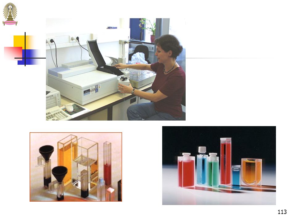


 รร. สตรีสมุทรปราการ.>")


>")

 แกมมา (Gamma) อุลตราไวโอเลต (UV) คิดเป็นประมาณร้อยละ 9 ของพลังงานทั้งหมด นอกนั้นเป็นรังสีที่มองเห็นร้อยละ.>")


 98.08% 100.02% จังหวัด.>")
 วิชาศึกษาธรรมชาติแสงและการมองเห็น.>")


>")
>")