ดาวน์โหลดงานนำเสนอ
งานนำเสนอกำลังจะดาวน์โหลด โปรดรอ

1
Chapter 10 : Finalizing Design Specification
Learning Objective Introduction The Process of Finalizing Design Specification Representing Design Specifications

2
Chapter 10 : Finalizing Design Specification
Introduction เนื่องจากความต้องการระบบในปัจจุบันนี้มีการพัฒนาเป็นไปอย่างรวดเร็วมากยิ่งขึ้นกว่าในอดีต การทำการตรวจสอบในแบบดั้งเดิมนั้นมักจะกระทำระหว่างการ Design และการ Implement โดยมักทำเมื่อเสร็จขั้นตอนการ Design แล้ว ส่วนวิธีการอื่นๆนั้นมักมีการทำในระหว่างขั้นการ Design และขั้นการ Implement ไปพร้อมๆกัน

3
Chapter 10 : Finalizing Design Specification
The Process of Finalizing Design Specifications Less costly to correct and detect errors during the design phase Quality requirement statements Quality requirements Deliverables and outcome

4
Chapter 10 : Finalizing Design Specification
Quality requirement statements Correct Feasible Necessary Prioritized Unambiguous Verifiable

5
Chapter 10 : Finalizing Design Specification
Quality requirements Completely Do not conflict with other requirement Easy to change without adversely affecting other requirements Traceable back to origin

6
Chapter 10 : Finalizing Design Specification
Deliverables and outcome Set of physical design specification contain detailed specifications for each part of the system

7
Chapter 10 : Finalizing Design Specification
Representing Design Specifications Traditional Methods 1.Pre-CASE 2.Documents written natural language and augmented with graphical models 3.specification documents

8
Chapter 10 : Finalizing Design Specification
Representing Design Specifications Structure Charts Shows how an information is organized in hierarchical models Shoes how part of the system are related to one another Shows breakdown of s system into programs and internal structures of programs written in 3 or 4 GLs

9
Chapter 10 : Finalizing Design Specification
Structure Charts Module เป็นส่วนประกอบการทำงานของระบบของเราในส่วนของหน้าที่งานต่างๆที่มีความสำคัญ ในการเขียนทุกครั้งต้องมีโหนดเริ่มต้นเสมอ (Root node) การเข้าและออกของข้อมูลไปยังโมดูลอื่นเป็นไปแบบทางเดียวเท่านั้น (One way) การสื่อสารระหว่างโมดูลทำได้โดยการส่งผ่าน Parameters
 การเข้าและออกของข้อมูลไปยังโมดูลอื่นเป็นไปแบบทางเดียวเท่านั้น (One way) การสื่อสารระหว่างโมดูลทำได้โดยการส่งผ่าน Parameters.")
10
Chapter 10 : Finalizing Design Specification
Structure Charts Symbol of Module Name Types of communication parameters Data couple : เป็นเครื่องมือที่ใช้ในการส่งผ่านข้อมูลกันระหว่างโมดูลต่างๆ Flag : เป็นเครื่องมือที่ใช้ควบคุมการทำงานของโปรแกรมว่าจะทำงานอย่างไร เช่น Error message

11
Chapter 10 : Finalizing Design Specification
Structure Charts Symbol of communication parameters Data couple Flag

12
Chapter 10 : Finalizing Design Specification
Structure Charts Symbol of Specials Module Diamond : Have condition to selected Name

13
Chapter 10 : Finalizing Design Specification
Structure Charts Symbol of Specials Module Curve line : Repeatedly until terminating condition is met Name

14
Chapter 10 : Finalizing Design Specification
Structure Charts Symbol of Specials Module Predefined Module : เป็นโมดูลที่เราเคยกล่าวถึงหรือมีอยู่ก่อนหน้านี้แล้ว Name

15
Chapter 10 : Finalizing Design Specification
Structure Charts Symbol of Specials Module Embedded Module (Hat) : เป็นโมดูลที่อยู่ด้านล่างที่มีความสำคัญแต่มีคำสั่งไม่เยอะเลยฝังไว้กับตัวด้านบนแทน Name
 : เป็นโมดูลที่อยู่ด้านล่างที่มีความสำคัญแต่มีคำสั่งไม่เยอะเลยฝังไว้กับตัวด้านบนแทน. Name.")
16
Chapter 10 : Finalizing Design Specification
Design Structure Charts Approach การออกแบบนั้นมีพื้นฐานมาจาก DFD ที่ออกแบบมาแล้วข้างต้นแล้วทำการปรับให้มีคุณภาพจากนั้นทำการแบ่งประเภทของStructure Charts โดยสามารถแบ่งได้ 2 รูปแบบตามการไหลของข้อมูล Type of Structure Charts Transform flow Transaction flow

17
Chapter 10 : Finalizing Design Specification
Design Structure Charts Approach Transform flow Find the processing process Find the Input (Afferent) and the Output (Efferent)
 and the Output (Efferent)")
18
Chapter 10 : Finalizing Design Specification
Design Structure Charts Approach Steps to design Transform flow and Transaction flow Find the processing process Find the Input (Afferent) and the Output (Efferent)
 and the Output (Efferent)")
19
Chapter 10 : Finalizing Design Specification
Design Structure Charts Approach Steps to design Transform flow Step 1 : ทำการตั้ง Module Commander อยู่ในระดับที่ 1 ซึ่งเป็น process module ที่เรียกใช้ process module อื่นๆ เรามักตั้งชื่อว่า Main Menu Step 2 : ทำการตั้งระดับที่ 2 ซึ่งเป็น Process Afferent สุดท้ายที่เจอหรือก็คือในส่วนของ Input นั้นเอง และทำไปเรื่อยๆจนกว่าจะครบในส่วนของ Afferent ทั้งหมด Step 3 : ตั้ง Transformation process module ซึ่งถ้ามีเพียง Process เดียวก็เขียนได้เลยแต่ถ้ามีมากกว่า ต้องมี Transformation Controller ก่อน

20
Chapter 10 : Finalizing Design Specification
Design Structure Charts Approach Steps to design Transform flow Step 4 : พิจารณาหา Efferent (Output) เช่นเดียวกันกับกรณีของ Afferent (Input) แต่ในส่วนนี้เราจะทำการเขียนไว้ในส่วนขวามือของTransform module Main Menu Transform Controller Input Output B A D C TA TB OA OB
 เช่นเดียวกันกับกรณีของ Afferent (Input) แต่ในส่วนนี้เราจะทำการเขียนไว้ในส่วนขวามือของTransform module. Main Menu. Transform. Controller. Input. Output. B. A. D. C. TA. TB. OA. OB.")
21
Chapter 10 : Finalizing Design Specification
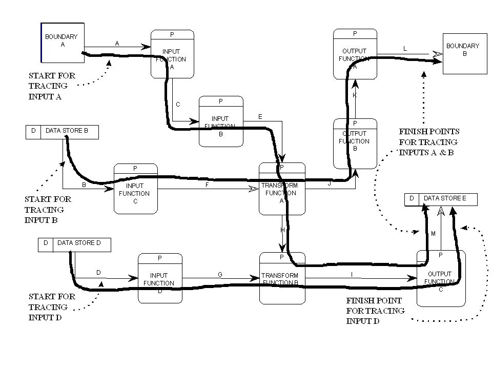
Design Structure Charts Approach Transform flow A C B D E F H G INPUT TRANSFORMATION OUTPUT

22
Chapter 10 : Finalizing Design Specification
Design Structure Charts Approach Steps to design Transaction flow Step 1 : ทำการตั้ง Module Commander อยู่ในระดับที่ 1 ซึ่งเป็น process module ที่เรียกใช้ process module อื่นๆ เรามักตั้งชื่อว่า Main Menu Step 2 : ทำการตั้งระดับที่ 2 ซึ่งเป็น Process Afferent สุดท้ายที่เจอหรือก็คือในส่วนของ Input นั้นเอง และทำไปเรื่อยๆจนกว่าจะครบในส่วนของ Afferent ทั้งหมด Step 3 : ตั้ง Transaction process module ซึ่งถ้ามีเพียง Process เดียวก็เขียนได้เลยแต่ถ้ามีมากกว่า ต้องมี Transaction Controller ก่อน

23
Chapter 10 : Finalizing Design Specification
Design Structure Charts Approach Steps to design Transaction flow Step 4 : พิจารณาหา Efferent (Output) เช่นเดียวกันกับกรณีของ Afferent (Input) แต่ในส่วนนี้เราจะทำการเขียนไว้ในส่วนขวามือของTransaction module Main Menu Transaction Controller Input Output B A D C TA TB OA OB
 เช่นเดียวกันกับกรณีของ Afferent (Input) แต่ในส่วนนี้เราจะทำการเขียนไว้ในส่วนขวามือของTransaction module. Main Menu. Transaction. Controller. Input. Output. B. A. D. C. TA. TB. OA. OB.")
24
Chapter 10 : Finalizing Design Specification
Design Structure Charts Approach Transaction flow A C B D E F H INPUT TRANSACTION OUTPUT

25
Structure Chart Quality Assurance Checks
Chapter 10 : Finalizing Design Specification Structure Chart Quality Assurance Checks Coupling Cohesion

26
Chapter 10 : Finalizing Design Specification
Coupling: Types of coupling: (from best to worst) Data coupling — two modules are said to be data coupled if their dependency is based on the fact that they communicate by passing of data. Stamp coupling — two modules are said to be stamp coupled if their communication of data is in the form of an entire data structure or record.
 Data coupling — two modules are said to be data coupled if their dependency is based on the fact that they communicate by passing of data. Stamp coupling — two modules are said to be stamp coupled if their communication of data is in the form of an entire data structure or record.")
27
Chapter 10 : Finalizing Design Specification
Coupling: Types of coupling: (from best to worst) Control coupling — two modules are said to be control coupled if their dependency is based on the fact that they communicate by passing of control information or flags. Common coupling — modules are said to be common coupled if they refer to the same global data area. Content coupling — two modules are said to be content coupled (also referred to as hybrid coupled) when one module actually modifies the procedural contents of another module.
 Control coupling — two modules are said to be control coupled if their dependency is based on the fact that they communicate by passing of control information or flags. Common coupling — modules are said to be common coupled if they refer to the same global data area. Content coupling — two modules are said to be content coupled (also referred to as hybrid coupled) when one module actually modifies the procedural contents of another module.")
28
Chapter 10 : Finalizing Design Specification
Cohesion: (from most desirable to least desirable) Functional cohesion — are modules whose instruction are related because they collectively work together to accomplish a single well-define function. Sequential cohesion — are modules whose instructions are related because the output data from one instruction is used as input data to the next instruction.
 Functional cohesion — are modules whose instruction are related because they collectively work together to accomplish a single well-define function. Sequential cohesion — are modules whose instructions are related because the output data from one instruction is used as input data to the next instruction.")
29
Chapter 10 : Finalizing Design Specification
Cohesion: (from most desirable to least desirable) Communicational cohesion — are modules whose instructions accomplish tasks that utilize the same piece(s) of data. Procedural cohesion — are modules whose instructions accomplish different tasks, yet have been combined because there is a specific order in which the tasks are to be completed.
 Communicational cohesion — are modules whose instructions accomplish tasks that utilize the same piece(s) of data. Procedural cohesion — are modules whose instructions accomplish different tasks, yet have been combined because there is a specific order in which the tasks are to be completed.")
30
Chapter 10 : Finalizing Design Specification
Cohesion: (continued) Temporal cohesion — are modules whose instructions appear to have been grouped together into a module because of “time”. Logical cohesion — are modules that contain instructions that appear to be related because they fall into the same logical class of functions. Coincidental cohesion — are modules that contain instructions that have little or no relationship to one another.
 Temporal cohesion — are modules whose instructions appear to have been grouped together into a module because of time . Logical cohesion — are modules that contain instructions that appear to be related because they fall into the same logical class of functions. Coincidental cohesion — are modules that contain instructions that have little or no relationship to one another.")
31
Types of Data Flow Transform flow Transaction flow

32
Central Transform Afferent Efferent

34
Example of Transform

35
Example of Transaction

36
Example of Transaction

งานนำเสนอที่คล้ายกัน
 ในช่วงยุค Internet เพิ่ง เริ่มต้น เป็นบริษัทที่ดำเนินงานทางด้าน.>")


![คำสั่ง DISPLAY รูปแบบที่ 1 DISPLAY identifier-1, identifier-2 … literal-1 literal-2 [ UPON mnemonic-name ] ตัวอย่าง DISPLAY STUDENT-NAME. DISPLAY.](/7/1925791/big_thumb.jpg "คำสั่ง DISPLAY รูปแบบที่ 1 DISPLAY identifier-1, identifier-2 … literal-1 literal-2 [ UPON mnemonic-name ] ตัวอย่าง DISPLAY STUDENT-NAME. DISPLAY.>")

>")


